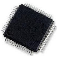
MC56F8257MLH Freescale Semiconductor, MC56F8257MLH Datasheet - Page 317

MC56F8257MLH
Manufacturer Part Number
MC56F8257MLH
Description
DSC 64K FLASH 60MHZ 64-LQFP
Manufacturer
Freescale Semiconductor
Series
56F8xxxr
Datasheets
1.TWR-56F8257.pdf
(88 pages)
2.MC56F8245VLD.pdf
(14 pages)
3.MC56F8245VLD.pdf
(2 pages)
4.MC56F8245VLD.pdf
(629 pages)
Specifications of MC56F8257MLH
Core Processor
56800E
Core Size
16-Bit
Speed
60MHz
Connectivity
CAN, I²C, LIN, SCI, SPI
Peripherals
LVD, POR, PWM, WDT
Number Of I /o
54
Program Memory Size
64KB (32K x 16)
Program Memory Type
FLASH
Ram Size
4K x 16
Voltage - Supply (vcc/vdd)
3 V ~ 3.6 V
Data Converters
A/D 16x12b, D/A 1x12b
Oscillator Type
Internal
Operating Temperature
-40°C ~ 105°C
Package / Case
64-LQFP
Product
DSCs
Processor Series
56800E
Core
56800E
Device Million Instructions Per Second
60 MIPs
Maximum Clock Frequency
60 MHz
Number Of Programmable I/os
54
Data Ram Size
8 KB
Operating Supply Voltage
3.3 V
Maximum Operating Temperature
+ 105 C
Mounting Style
SMD/SMT
Minimum Operating Temperature
- 40 C
On-chip Adc
12 bit, 8 Channel
Lead Free Status / RoHS Status
Lead free / RoHS Compliant
Eeprom Size
-
Lead Free Status / Rohs Status
Details
Available stocks
Company
Part Number
Manufacturer
Quantity
Price
Company:
Part Number:
MC56F8257MLH
Manufacturer:
MOTOLOLA
Quantity:
560
Company:
Part Number:
MC56F8257MLH
Manufacturer:
Freescale Semiconductor
Quantity:
10 000
- TWR-56F8257 PDF datasheet
- MC56F8245VLD PDF datasheet #2
- MC56F8245VLD PDF datasheet #3
- MC56F8245VLD PDF datasheet #4
- Current page: 317 of 629
- Download datasheet (4Mb)
The interrupt signals in each port are ORed together, presenting only a single interrupt
per port to the interrupt controller. The interrupt service routine must then check the
contents of the interrupt pending register to determine which pin(s) caused the interrupt.
External interrupt sources do not need to remain asserted because the detection
mechanism is edge sensitive.
9.5 Clocks and Resets
The GPIO module runs at standard system bus speeds and assumes reset states as defined
in the device data sheet. Reset occurs whenever any source of system reset occurs (POR,
external reset, COP reset, and so on).
Freescale Semiconductor
2. Hardware interrupt from the pin
Write ones to the interrupt assert register to generate the software interrupt. The
interrupt pending register records the value of the interrupt assert register. Clear the
the interrupt pending register by writing zeroes to the the interrupt assert register.
When a GPIO pin is used as an external interrupt source, its IEN bit in the interrupt
enable register is set to 1 and the interrupt assert register must be set to 0. The
interrupt polarity register must be set to 1 for a falling edge interrupt and to 0 for a
rising edge interrupt. When the signal at the pin transitions from high to low or low
to high, the value is seen at the interrupt edge sensitive register and recorded by the
interrupt pending register.
When a software interrupt is asserted, the interrupt polarity
register, interrupt edge sensitive register, and the interrupt
enable register must be zero to guarantee that the interrupt
registered in the interrupt pending register is due only to the
interrupt assert register.
MC56F825x/4x Reference Manual, Rev. 2, 10/2010
Preliminary
NOTE
Chapter 9 General-Purpose Input/Output (GPIO)
317
Related parts for MC56F8257MLH
Image
Part Number
Description
Manufacturer
Datasheet
Request
R
Part Number:
Description:
Manufacturer:
Freescale Semiconductor, Inc
Datasheet:
Part Number:
Description:
Manufacturer:
Freescale Semiconductor, Inc
Datasheet:
Part Number:
Description:
Manufacturer:
Freescale Semiconductor, Inc
Datasheet:
Part Number:
Description:
Manufacturer:
Freescale Semiconductor, Inc
Datasheet:
Part Number:
Description:
Manufacturer:
Freescale Semiconductor, Inc
Datasheet:
Part Number:
Description:
Manufacturer:
Freescale Semiconductor, Inc
Datasheet:
Part Number:
Description:
Manufacturer:
Freescale Semiconductor, Inc
Datasheet:
Part Number:
Description:
Manufacturer:
Freescale Semiconductor, Inc
Datasheet:
Part Number:
Description:
Manufacturer:
Freescale Semiconductor, Inc
Datasheet:
Part Number:
Description:
Manufacturer:
Freescale Semiconductor, Inc
Datasheet:
Part Number:
Description:
Manufacturer:
Freescale Semiconductor, Inc
Datasheet:
Part Number:
Description:
Manufacturer:
Freescale Semiconductor, Inc
Datasheet:
Part Number:
Description:
Manufacturer:
Freescale Semiconductor, Inc
Datasheet:
Part Number:
Description:
Manufacturer:
Freescale Semiconductor, Inc
Datasheet:
Part Number:
Description:
Manufacturer:
Freescale Semiconductor, Inc
Datasheet:


