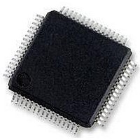
MC56F8257MLH Freescale Semiconductor, MC56F8257MLH Datasheet - Page 551

MC56F8257MLH
Manufacturer Part Number
MC56F8257MLH
Description
DSC 64K FLASH 60MHZ 64-LQFP
Manufacturer
Freescale Semiconductor
Series
56F8xxxr
Datasheets
1.TWR-56F8257.pdf
(88 pages)
2.MC56F8245VLD.pdf
(14 pages)
3.MC56F8245VLD.pdf
(2 pages)
4.MC56F8245VLD.pdf
(629 pages)
Specifications of MC56F8257MLH
Core Processor
56800E
Core Size
16-Bit
Speed
60MHz
Connectivity
CAN, I²C, LIN, SCI, SPI
Peripherals
LVD, POR, PWM, WDT
Number Of I /o
54
Program Memory Size
64KB (32K x 16)
Program Memory Type
FLASH
Ram Size
4K x 16
Voltage - Supply (vcc/vdd)
3 V ~ 3.6 V
Data Converters
A/D 16x12b, D/A 1x12b
Oscillator Type
Internal
Operating Temperature
-40°C ~ 105°C
Package / Case
64-LQFP
Product
DSCs
Processor Series
56800E
Core
56800E
Device Million Instructions Per Second
60 MIPs
Maximum Clock Frequency
60 MHz
Number Of Programmable I/os
54
Data Ram Size
8 KB
Operating Supply Voltage
3.3 V
Maximum Operating Temperature
+ 105 C
Mounting Style
SMD/SMT
Minimum Operating Temperature
- 40 C
On-chip Adc
12 bit, 8 Channel
Lead Free Status / RoHS Status
Lead free / RoHS Compliant
Eeprom Size
-
Lead Free Status / Rohs Status
Details
Available stocks
Company
Part Number
Manufacturer
Quantity
Price
Company:
Part Number:
MC56F8257MLH
Manufacturer:
MOTOLOLA
Quantity:
560
Company:
Part Number:
MC56F8257MLH
Manufacturer:
Freescale Semiconductor
Quantity:
10 000
- TWR-56F8257 PDF datasheet
- MC56F8245VLD PDF datasheet #2
- MC56F8245VLD PDF datasheet #3
- MC56F8245VLD PDF datasheet #4
- Current page: 551 of 629
- Download datasheet (4Mb)
16.2.15 STOP Disable Register 0 (SIM_SD0)
By default, peripheral clocks are disabled in stop mode to maximize power savings. The
stop disable controls in the SD override individual peripheral clocks so that they continue
to operate in stop mode. Because asserting an interrupt makes the system return to run
mode, this feature is provided so that selected peripherals can continue to operate in stop
mode for the purpose of generating a wakeup interrupt.
For power-conscious applications, only an essential set of peripherals should be
configured to remain operational in stop mode.
Peripherals should be put in a non-operating (disabled) configuration before the device
enters stop mode unless their corresponding STOP Disable control is set to 1. Refer to the
peripheral user guide for details. IP bus reads and writes cannot be made to a module
with its clock disabled.
The SD register controls have lower priority than the PCE (Peripheral Clock Enable)
register controls. If the peripheral PCE control is cleared to 0, the peripheral clock is
disabled in all modes, including stop mode.
Address: SIM_SD0 – F0E0h base + Fh offset = F0EFh
Freescale Semiconductor
Reset
Read
Write
Bit
PWMCH1
PWMCH2
PWMCH3
Field
2
1
0
TA0
15
0
TA1
14
0
PWM Channel 1 IPBus Clock Enable
PWM Channel 2 IPBus Clock Enable
PWM Channel 3 IPBus Clock Enable
Each bit enables peripheral clocking to the indicated peripheral.
0
1
The corresponding peripheral is not clocked
The corresponding peripheral is clocked
TA2
13
0
TA3
12
0
MC56F825x/4x Reference Manual, Rev. 2, 10/2010
SIM_PCE2 field descriptions (continued)
TB0
11
0
TB1
10
0
TB2
0
9
Preliminary
TB3
0
8
Description
ADC
0
7
0
6
Chapter 16 System Integration Module (SIM)
GPIO
B
0
5
0
4
0
3
GPIO
E
0
2
GPIO
F
0
1
0
0
0
551
Related parts for MC56F8257MLH
Image
Part Number
Description
Manufacturer
Datasheet
Request
R
Part Number:
Description:
Manufacturer:
Freescale Semiconductor, Inc
Datasheet:
Part Number:
Description:
Manufacturer:
Freescale Semiconductor, Inc
Datasheet:
Part Number:
Description:
Manufacturer:
Freescale Semiconductor, Inc
Datasheet:
Part Number:
Description:
Manufacturer:
Freescale Semiconductor, Inc
Datasheet:
Part Number:
Description:
Manufacturer:
Freescale Semiconductor, Inc
Datasheet:
Part Number:
Description:
Manufacturer:
Freescale Semiconductor, Inc
Datasheet:
Part Number:
Description:
Manufacturer:
Freescale Semiconductor, Inc
Datasheet:
Part Number:
Description:
Manufacturer:
Freescale Semiconductor, Inc
Datasheet:
Part Number:
Description:
Manufacturer:
Freescale Semiconductor, Inc
Datasheet:
Part Number:
Description:
Manufacturer:
Freescale Semiconductor, Inc
Datasheet:
Part Number:
Description:
Manufacturer:
Freescale Semiconductor, Inc
Datasheet:
Part Number:
Description:
Manufacturer:
Freescale Semiconductor, Inc
Datasheet:
Part Number:
Description:
Manufacturer:
Freescale Semiconductor, Inc
Datasheet:
Part Number:
Description:
Manufacturer:
Freescale Semiconductor, Inc
Datasheet:
Part Number:
Description:
Manufacturer:
Freescale Semiconductor, Inc
Datasheet:


