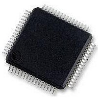
MC56F8257MLH Freescale Semiconductor, MC56F8257MLH Datasheet - Page 527

MC56F8257MLH
Manufacturer Part Number
MC56F8257MLH
Description
DSC 64K FLASH 60MHZ 64-LQFP
Manufacturer
Freescale Semiconductor
Series
56F8xxxr
Datasheets
1.TWR-56F8257.pdf
(88 pages)
2.MC56F8245VLD.pdf
(14 pages)
3.MC56F8245VLD.pdf
(2 pages)
4.MC56F8245VLD.pdf
(629 pages)
Specifications of MC56F8257MLH
Core Processor
56800E
Core Size
16-Bit
Speed
60MHz
Connectivity
CAN, I²C, LIN, SCI, SPI
Peripherals
LVD, POR, PWM, WDT
Number Of I /o
54
Program Memory Size
64KB (32K x 16)
Program Memory Type
FLASH
Ram Size
4K x 16
Voltage - Supply (vcc/vdd)
3 V ~ 3.6 V
Data Converters
A/D 16x12b, D/A 1x12b
Oscillator Type
Internal
Operating Temperature
-40°C ~ 105°C
Package / Case
64-LQFP
Product
DSCs
Processor Series
56800E
Core
56800E
Device Million Instructions Per Second
60 MIPs
Maximum Clock Frequency
60 MHz
Number Of Programmable I/os
54
Data Ram Size
8 KB
Operating Supply Voltage
3.3 V
Maximum Operating Temperature
+ 105 C
Mounting Style
SMD/SMT
Minimum Operating Temperature
- 40 C
On-chip Adc
12 bit, 8 Channel
Lead Free Status / RoHS Status
Lead free / RoHS Compliant
Eeprom Size
-
Lead Free Status / Rohs Status
Details
Available stocks
Company
Part Number
Manufacturer
Quantity
Price
Company:
Part Number:
MC56F8257MLH
Manufacturer:
MOTOLOLA
Quantity:
560
Company:
Part Number:
MC56F8257MLH
Manufacturer:
Freescale Semiconductor
Quantity:
10 000
- TWR-56F8257 PDF datasheet
- MC56F8245VLD PDF datasheet #2
- MC56F8245VLD PDF datasheet #3
- MC56F8245VLD PDF datasheet #4
- Current page: 527 of 629
- Download datasheet (4Mb)
Each of these clock sources can be selected to drive the remainder of the clock generation
circuitry. This circuitry allows direct use of the clock, or the clock can be used as an input
to the PLL which will generate a higher frequency clock for use within the chip.
The clock multiplexer (ZSRC MUX) selects the direct clock on power up. A different
clock source can be selected by writing to the PLL control register (CTRL). Once a new
clock source is selected, the new clock will be activated within four clock periods of the
new clock after the clock selection request is re-clocked by the current IPbus clock.
The postscaler output is guaranteed to be glitch free when changing the divide ratio.
Transitions to/from direct to postscaler frequencies are guaranteed to be glitch free
on the sys_clk_x2 clock. Before switching to the PLL, the PLL must be locked. The
OCCS Status Register (STAT) shows the status of the DSP core clock source. Because
the synchronizing circuit changes modes to avoid any glitches, the STAT ZCLOCK
source (ZSRCS) shows overlapping modes as an intermediate step. After PLL lock is
detected, the DSP core clock can be switched to the PLL by writing to the ZSRC field in
the CTRL register.
Frequencies going out of the OCCS are controlled by the postscaler and/or by the divide-
by ratio within the PLL. For proper operation of the PLL, the user must keep the VCO,
within the PLL, in its operational range of 120 MHz to 240 MHz. The output of the VCO
is depicted as F
ratio is the frequency at which the VCO runs.
The PLL lock time is 10 ms or less when coming from a powered down state to a power
up state. It is recommended when powering down, or powering up, to unselect the PLL as
the clocking source. Only after lock is achieved should the PLL be used as a valid
clocking source.
The following table shows the possible clock sources and configurations.
Freescale Semiconductor
• External ceramic resonator
• External crystal
• External clock source on either XTAL or GPIO port C0.
Relaxation Oscillator
Clock Source
pll
in the block diagram. The input frequency multiplied by the divide-by
Table 15-9. Clock Choices Without Crystal Oscillator
Clock Selected Configuration Steps
MC56F825x/4x Reference Manual, Rev. 2, 10/2010
Direct
Table continues on the next page...
Default.
1. Change TRIM as needed to obtain the desired clock rate
Preliminary
Chapter 15 On-Chip Clock Synthesis (OCCS)
527
Related parts for MC56F8257MLH
Image
Part Number
Description
Manufacturer
Datasheet
Request
R
Part Number:
Description:
Manufacturer:
Freescale Semiconductor, Inc
Datasheet:
Part Number:
Description:
Manufacturer:
Freescale Semiconductor, Inc
Datasheet:
Part Number:
Description:
Manufacturer:
Freescale Semiconductor, Inc
Datasheet:
Part Number:
Description:
Manufacturer:
Freescale Semiconductor, Inc
Datasheet:
Part Number:
Description:
Manufacturer:
Freescale Semiconductor, Inc
Datasheet:
Part Number:
Description:
Manufacturer:
Freescale Semiconductor, Inc
Datasheet:
Part Number:
Description:
Manufacturer:
Freescale Semiconductor, Inc
Datasheet:
Part Number:
Description:
Manufacturer:
Freescale Semiconductor, Inc
Datasheet:
Part Number:
Description:
Manufacturer:
Freescale Semiconductor, Inc
Datasheet:
Part Number:
Description:
Manufacturer:
Freescale Semiconductor, Inc
Datasheet:
Part Number:
Description:
Manufacturer:
Freescale Semiconductor, Inc
Datasheet:
Part Number:
Description:
Manufacturer:
Freescale Semiconductor, Inc
Datasheet:
Part Number:
Description:
Manufacturer:
Freescale Semiconductor, Inc
Datasheet:
Part Number:
Description:
Manufacturer:
Freescale Semiconductor, Inc
Datasheet:
Part Number:
Description:
Manufacturer:
Freescale Semiconductor, Inc
Datasheet:


