D6417729RHF200BV Renesas Electronics America, D6417729RHF200BV Datasheet - Page 307
D6417729RHF200BV
Manufacturer Part Number
D6417729RHF200BV
Description
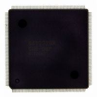
IC SUPER H MPU ROMLESS 208QFP
Manufacturer
Renesas Electronics America
Series
SuperH® SH7700r
Datasheet
1.D6417729RF133BV.pdf
(857 pages)
Specifications of D6417729RHF200BV
Core Processor
SH-3 DSP
Core Size
32-Bit
Speed
200MHz
Connectivity
EBI/EMI, FIFO, IrDA, SCI, SmartCard
Peripherals
DMA, POR, WDT
Number Of I /o
96
Program Memory Type
ROMless
Ram Size
32K x 8
Voltage - Supply (vcc/vdd)
1.85 V ~ 2.15 V
Data Converters
A/D 8x10b; D/A 2x8b
Oscillator Type
Internal
Operating Temperature
-20°C ~ 75°C
Package / Case
208-QFP Exposed Pad, 208-eQFP, 208-HQFP
Lead Free Status / RoHS Status
Lead free / RoHS Compliant
Eeprom Size
-
Program Memory Size
-
Available stocks
Company
Part Number
Manufacturer
Quantity
Price
Company:

Part Number:
D6417729RHF200BV
Manufacturer:
EVERLIGHT
Quantity:
1 000
Company:
Part Number:
D6417729RHF200BV
Manufacturer:
Renesas Electronics America
Quantity:
10 000


10.5
The frequency of the internal clock and peripheral clock can be changed either by changing the
multiplication ratio of PLL circuit 1 or by changing the division ratios of dividers 1 and 2. All of
these are controlled by software through the frequency control register. The methods are described
below.
10.5.1
A PLL settling time is required when the multiplication rate of PLL circuit 1 is changed. The on-
chip WDT counts the settling time.
1. In the initial state, the multiplication rate of PLL circuit 1 is 1.
2. Set a value that will become the specified oscillation settling time in the WDT and stop the
3. Set the desired value in the STC2, STC1, and STC0 bits. The division ratio can also be set in
4. The processor pauses internally and the WDT starts incrementing. In clock modes 0–2 and 7,
5. Supply of the clock that has been set begins at WDT count overflow, and the processor begins
10.5.2
The WDT will not count unless the multiplication ratio is changed simultaneously.
1. In the initial state, IFC2–IFC0
2. Set the IFC2, IFC1, IFC0, PFC2, PFC1, and PFC0 bits to the new division ratio. The values
3. The clock is immediately supplied at the new division ratio.
10.5.3
If the following three conditions are all met, FRQCR should not be changed when a transfer using
the DMAC is in progress.
WDT. The following must be set:
WTCSR register TME bit
WTCSR register CKS2–CKS0 bits: Division ratio of WDT count clock
WTCNT counter: Initial counter value
the IFC2–IFC0 bits and PFC2–PFC0 bits.
the internal and peripheral clocks both stop (except for the peripheral clock supplied to the
WDT).
operating again. The WDT stops after it overflows.
that can be set are limited by the clock mode and the multiplication ratio of PLL circuit 1. Note
that if the wrong value is set, the processor will malfunction.
Bits IFC2 to IFC0 are changed.
Changing the Frequency
Changing the Multiplication Rate
Changing the Division Ratio
Notes on Changing the Frequency
0: WDT stops
000 and PFC2–PFC0
010.
Rev. 5.0, 09/03, page 259 of 806
Related parts for D6417729RHF200BV
Image
Part Number
Description
Manufacturer
Datasheet
Request
R

Part Number:
Description:
KIT STARTER FOR M16C/29
Manufacturer:
Renesas Electronics America
Datasheet:

Part Number:
Description:
KIT STARTER FOR R8C/2D
Manufacturer:
Renesas Electronics America
Datasheet:

Part Number:
Description:
R0K33062P STARTER KIT
Manufacturer:
Renesas Electronics America
Datasheet:

Part Number:
Description:
KIT STARTER FOR R8C/23 E8A
Manufacturer:
Renesas Electronics America
Datasheet:

Part Number:
Description:
KIT STARTER FOR R8C/25
Manufacturer:
Renesas Electronics America
Datasheet:

Part Number:
Description:
KIT STARTER H8S2456 SHARPE DSPLY
Manufacturer:
Renesas Electronics America
Datasheet:

Part Number:
Description:
KIT STARTER FOR R8C38C
Manufacturer:
Renesas Electronics America
Datasheet:

Part Number:
Description:
KIT STARTER FOR R8C35C
Manufacturer:
Renesas Electronics America
Datasheet:

Part Number:
Description:
KIT STARTER FOR R8CL3AC+LCD APPS
Manufacturer:
Renesas Electronics America
Datasheet:
Part Number:
Description:
KIT STARTER FOR RX610
Manufacturer:
Renesas Electronics America
Datasheet:

Part Number:
Description:
KIT STARTER FOR R32C/118
Manufacturer:
Renesas Electronics America
Datasheet:

Part Number:
Description:
KIT DEV RSK-R8C/26-29
Manufacturer:
Renesas Electronics America
Datasheet:

Part Number:
Description:
KIT STARTER FOR SH7124
Manufacturer:
Renesas Electronics America
Datasheet:

Part Number:
Description:
KIT STARTER FOR H8SX/1622
Manufacturer:
Renesas Electronics America
Datasheet:

Part Number:
Description:
KIT DEV FOR SH7203
Manufacturer:
Renesas Electronics America
Datasheet: