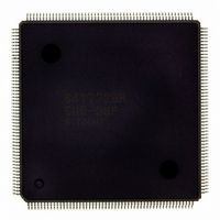
D6417729RHF200BV Renesas Electronics America, D6417729RHF200BV Datasheet - Page 35

D6417729RHF200BV
Manufacturer Part Number
D6417729RHF200BV
Description
IC SUPER H MPU ROMLESS 208QFP
Manufacturer
Renesas Electronics America
Series
SuperH® SH7700r
Datasheet
1.D6417729RF133BV.pdf
(857 pages)
Specifications of D6417729RHF200BV
Core Processor
SH-3 DSP
Core Size
32-Bit
Speed
200MHz
Connectivity
EBI/EMI, FIFO, IrDA, SCI, SmartCard
Peripherals
DMA, POR, WDT
Number Of I /o
96
Program Memory Type
ROMless
Ram Size
32K x 8
Voltage - Supply (vcc/vdd)
1.85 V ~ 2.15 V
Data Converters
A/D 8x10b; D/A 2x8b
Oscillator Type
Internal
Operating Temperature
-20°C ~ 75°C
Package / Case
208-QFP Exposed Pad, 208-eQFP, 208-HQFP
Lead Free Status / RoHS Status
Lead free / RoHS Compliant
Eeprom Size
-
Program Memory Size
-
Available stocks
Company
Part Number
Manufacturer
Quantity
Price
Company:
Part Number:
D6417729RHF200BV
Manufacturer:
EVERLIGHT
Quantity:
1 000
Company:
Part Number:
D6417729RHF200BV
Manufacturer:
Renesas Electronics America
Quantity:
10 000
- Current page: 35 of 857
- Download datasheet (5Mb)
Figures
Figure 1.1
Figure 1.2
Figure 1.3
Figure 2.1
Figure 2.2
Figure 2.3
Figure 2.4
Figure 2.5
Figure 2.6
Figure 2.7
Figure 2.8
Figure 2.9
Figure 2.10
Figure 2.11
Figure 2.12
Figure 2.13
Figure 2.14
Figure 2.15
Figure 2.16
Figure 2.17
Figure 3.1
Figure 3.2
Figure 3.3
Figure 3.4
Figure 3.5
Figure 3.6
Figure 3.7
Figure 3.8
Figure 3.9
Figure 3.10
Figure 3.11
Figure 3.12
Figure 3.13
Figure 3.14
Figure 3.15
Figure 4.1
Figure 4.2
Figure 4.3
Figure 5.1
Figure 5.2
Figure 5.3
Figure 5.4
Pin Assignment (BP-240A)..................................................................................
Examples of Conditional Operations and Data Transfer Instructions .................. 88
Synonym Problem ................................................................................................ 109
Block Diagram .....................................................................................................
Pin Assignment (FP-208C, FP-208E) ..................................................................
Register Configuration in Each Processing Mode (1) .......................................... 21
Register Configuration in Each Processing Mode (2) .......................................... 22
General Purpose Registers (Not in DSP Mode) ................................................... 23
General Purpose Registers (DSP Mode) .............................................................. 24
Control Registers.................................................................................................. 27
System Registers .................................................................................................. 30
DSP Registers....................................................................................................... 32
Connections of DSP Registers and Buses ............................................................ 34
Longword Operand .............................................................................................. 35
Data Formats ........................................................................................................ 36
Byte, Word, and Longword Alignment ................................................................ 37
X and Y Data Transfer Addressing ...................................................................... 46
Single Data Transfer Addressing.......................................................................... 47
Modulo Addressing .............................................................................................. 48
DSP Instruction Formats ...................................................................................... 53
Sample Parallel Instruction Program.................................................................... 80
MMU Functions ................................................................................................... 93
Virtual Address Space Mapping........................................................................... 95
MMU Register Contents ...................................................................................... 98
Overall Configuration of the TLB ........................................................................ 99
Virtual Address and TLB Structure...................................................................... 100
TLB Indexing (IX = 1) ......................................................................................... 101
TLB Indexing (IX = 0) ......................................................................................... 102
Objects of Address Comparison ........................................................................... 103
Operation of LDTLB Instruction.......................................................................... 107
MMU Exception Generation Flowchart ............................................................... 114
MMU Exception Signals in Instruction Fetch ...................................................... 115
MMU Exception Signals in Data Access ............................................................. 116
MMU Exception in Repeat Loop ......................................................................... 117
Specifying Address and Data for Memory-Mapped TLB Access ........................ 120
Vector Table......................................................................................................... 124
Example of Acceptance Order of General Exceptions ......................................... 127
Bit Configurations of EXPEVT, INTEVT, INTEVT2, and TRA Registers......... 130
Cache Structure .................................................................................................... 144
CCR Register Configuration ................................................................................ 146
CCR2 Register Configuration .............................................................................. 147
Cache Search Scheme (Normal Mode) ................................................................ 149
Rev. 5.0, 09/03, page xxxiii of xlvi
7
8
9
Related parts for D6417729RHF200BV
Image
Part Number
Description
Manufacturer
Datasheet
Request
R

Part Number:
Description:
KIT STARTER FOR M16C/29
Manufacturer:
Renesas Electronics America
Datasheet:

Part Number:
Description:
KIT STARTER FOR R8C/2D
Manufacturer:
Renesas Electronics America
Datasheet:

Part Number:
Description:
R0K33062P STARTER KIT
Manufacturer:
Renesas Electronics America
Datasheet:

Part Number:
Description:
KIT STARTER FOR R8C/23 E8A
Manufacturer:
Renesas Electronics America
Datasheet:

Part Number:
Description:
KIT STARTER FOR R8C/25
Manufacturer:
Renesas Electronics America
Datasheet:

Part Number:
Description:
KIT STARTER H8S2456 SHARPE DSPLY
Manufacturer:
Renesas Electronics America
Datasheet:

Part Number:
Description:
KIT STARTER FOR R8C38C
Manufacturer:
Renesas Electronics America
Datasheet:

Part Number:
Description:
KIT STARTER FOR R8C35C
Manufacturer:
Renesas Electronics America
Datasheet:

Part Number:
Description:
KIT STARTER FOR R8CL3AC+LCD APPS
Manufacturer:
Renesas Electronics America
Datasheet:

Part Number:
Description:
KIT STARTER FOR RX610
Manufacturer:
Renesas Electronics America
Datasheet:

Part Number:
Description:
KIT STARTER FOR R32C/118
Manufacturer:
Renesas Electronics America
Datasheet:

Part Number:
Description:
KIT DEV RSK-R8C/26-29
Manufacturer:
Renesas Electronics America
Datasheet:

Part Number:
Description:
KIT STARTER FOR SH7124
Manufacturer:
Renesas Electronics America
Datasheet:

Part Number:
Description:
KIT STARTER FOR H8SX/1622
Manufacturer:
Renesas Electronics America
Datasheet:

Part Number:
Description:
KIT DEV FOR SH7203
Manufacturer:
Renesas Electronics America
Datasheet:


