D6417729RHF200BV Renesas Electronics America, D6417729RHF200BV Datasheet - Page 41
D6417729RHF200BV
Manufacturer Part Number
D6417729RHF200BV
Description
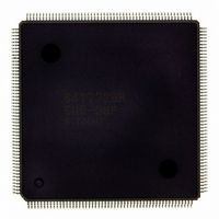
IC SUPER H MPU ROMLESS 208QFP
Manufacturer
Renesas Electronics America
Series
SuperH® SH7700r
Datasheet
1.D6417729RF133BV.pdf
(857 pages)
Specifications of D6417729RHF200BV
Core Processor
SH-3 DSP
Core Size
32-Bit
Speed
200MHz
Connectivity
EBI/EMI, FIFO, IrDA, SCI, SmartCard
Peripherals
DMA, POR, WDT
Number Of I /o
96
Program Memory Type
ROMless
Ram Size
32K x 8
Voltage - Supply (vcc/vdd)
1.85 V ~ 2.15 V
Data Converters
A/D 8x10b; D/A 2x8b
Oscillator Type
Internal
Operating Temperature
-20°C ~ 75°C
Package / Case
208-QFP Exposed Pad, 208-eQFP, 208-HQFP
Lead Free Status / RoHS Status
Lead free / RoHS Compliant
Eeprom Size
-
Program Memory Size
-
Available stocks
Company
Part Number
Manufacturer
Quantity
Price
Company:

Part Number:
D6417729RHF200BV
Manufacturer:
EVERLIGHT
Quantity:
1 000
Company:
Part Number:
D6417729RHF200BV
Manufacturer:
Renesas Electronics America
Quantity:
10 000


Figure 24.4
Figure 24.5
Figure 24.6
Figure 24.7
Figure 24.8
Figure 24.9
Figure 24.10 PLL Synchronization Settling Time in Case of IRQ/IRL Interrupt ...................... 712
Figure 24.11 Reset Input Timing............................................................................................... 714
Figure 24.12 Interrupt Signal Input Timing............................................................................... 714
Figure 24.13 IRQOUT Timing .................................................................................................. 714
Figure 24.14 Bus Release Timing.............................................................................................. 715
Figure 24.15 Pin Drive Timing at Standby................................................................................ 715
Figure 24.16 Basic Bus Cycle (No Wait) .................................................................................. 718
Figure 24.17 Basic Bus Cycle (One Wait)................................................................................. 719
Figure 24.18 Basic Bus Cycle (External Wait, WAITSEL = 1) ................................................ 720
Figure 24.19 Burst ROM Bus Cycle (No Wait) ........................................................................ 721
Figure 24.20 Burst ROM Bus Cycle (Two Waits) .................................................................... 722
Figure 24.21 Burst ROM Bus Cycle (External Wait, WAITSEL = 1) ...................................... 723
Figure 24.22 Synchronous DRAM Read Bus Cycle (RCD
Figure 24.23 Synchronous DRAM Read Bus Cycle (RCD
Figure 24.24 Synchronous DRAM Read Bus Cycle (Burst Read (Single Read
Figure 24.25 Synchronous DRAM Read Bus Cycle (Burst Read (Single Read
Figure 24.26 Synchronous DRAM Write Bus Cycle (RCD
Figure 24.27 Synchronous DRAM Write Bus Cycle (RCD
Figure 24.28 Synchronous DRAM Write Bus Cycle (Burst Write (Single Write
Figure 24.29 Synchronous DRAM Write Bus Cycle (Burst Mode (Single Write
Figure 24.30 Synchronous DRAM Burst Read Bus Cycle (RAS Down, Same Row Address,
Figure 24.31 Synchronous DRAM Burst Read Bus Cycle (RAS Down, Same Row Address,
Figure 24.32 Synchronous DRAM Burst Read Bus Cycle (RAS Down, Different Row
Figure 24.33 Synchronous DRAM Burst Read Bus Cycle
Figure 24.34 Synchronous DRAM Burst Write Bus Cycle (RAS Down, Same Row Address) 736
Figure 24.35 Synchronous DRAM Burst Write Bus Cycle (RAS Down, Different Row
Power-on Oscillation Settling Time ..................................................................... 709
Oscillation Settling Time on Return from Standby (Return by Reset) ................. 709
Oscillation Settling Time on Return from Standby (Return by NMI) .................. 710
Oscillation Settling Time on Return from Standby (Return by IRQ4 to IRQ0,
PINT0/1 and IRL3 to IRL0)................................................................................. 710
PLL Synchronization Settling Time during Standby Recovery (Reset or NMI) .. 711
PLL Synchronization Settling Time during Standby Recovery (IRQ/IRL or
PINT0/PINT1 Interrupt)....................................................................................... 711
RCD
CAS Latency 3, TPC
RCD
RCD
CAS Latency = 1)................................................................................................. 732
CAS Latency = 2)................................................................................................. 733
Address, TPC = 0, RCD = 0, CAS Latency = 1) .................................................. 734
(RAS Down, Different Row Address, TPC = 1, RCD = 0, CAS Latency = 1) .... 735
Address, TPC = 0, RCD = 0) ............................................................................... 737
0, CAS Latency
0, TPC
1, TPC
1, TRWL = 0) ........................................................................... 730
0, TRWL = 0) ........................................................................... 731
0) ................................................................................. 727
1, TPC 1) ................................................................. 726
0, CAS Latency
2, CAS Latency
0, TPC
2, TPC
Rev. 5.0, 09/03, page xxxix of xlvi
0, TRWL = 0)............ 728
1, TRWL = 1)............ 729
1, TPC
2, TPC
4),
4), RCD 1,
4),
4),
0) .. 724
1) .. 725
Related parts for D6417729RHF200BV
Image
Part Number
Description
Manufacturer
Datasheet
Request
R

Part Number:
Description:
KIT STARTER FOR M16C/29
Manufacturer:
Renesas Electronics America
Datasheet:

Part Number:
Description:
KIT STARTER FOR R8C/2D
Manufacturer:
Renesas Electronics America
Datasheet:

Part Number:
Description:
R0K33062P STARTER KIT
Manufacturer:
Renesas Electronics America
Datasheet:

Part Number:
Description:
KIT STARTER FOR R8C/23 E8A
Manufacturer:
Renesas Electronics America
Datasheet:

Part Number:
Description:
KIT STARTER FOR R8C/25
Manufacturer:
Renesas Electronics America
Datasheet:

Part Number:
Description:
KIT STARTER H8S2456 SHARPE DSPLY
Manufacturer:
Renesas Electronics America
Datasheet:

Part Number:
Description:
KIT STARTER FOR R8C38C
Manufacturer:
Renesas Electronics America
Datasheet:

Part Number:
Description:
KIT STARTER FOR R8C35C
Manufacturer:
Renesas Electronics America
Datasheet:

Part Number:
Description:
KIT STARTER FOR R8CL3AC+LCD APPS
Manufacturer:
Renesas Electronics America
Datasheet:
Part Number:
Description:
KIT STARTER FOR RX610
Manufacturer:
Renesas Electronics America
Datasheet:

Part Number:
Description:
KIT STARTER FOR R32C/118
Manufacturer:
Renesas Electronics America
Datasheet:

Part Number:
Description:
KIT DEV RSK-R8C/26-29
Manufacturer:
Renesas Electronics America
Datasheet:

Part Number:
Description:
KIT STARTER FOR SH7124
Manufacturer:
Renesas Electronics America
Datasheet:

Part Number:
Description:
KIT STARTER FOR H8SX/1622
Manufacturer:
Renesas Electronics America
Datasheet:

Part Number:
Description:
KIT DEV FOR SH7203
Manufacturer:
Renesas Electronics America
Datasheet: