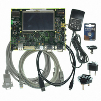
AT91SAM9G45-EKES Atmel, AT91SAM9G45-EKES Datasheet - Page 1114

AT91SAM9G45-EKES
Manufacturer Part Number
AT91SAM9G45-EKES
Description
KIT EVAL FOR AT91SAM9G45
Manufacturer
Atmel
Series
AT91SAM Smart ARMr
Type
MCUr
Datasheets
1.AT91SAM9G45-EKES.pdf
(56 pages)
2.AT91SAM9G45-EKES.pdf
(1218 pages)
3.AT91SAM9G45-EKES.pdf
(66 pages)
Specifications of AT91SAM9G45-EKES
Contents
Board
Processor To Be Evaluated
SAM9G45
Data Bus Width
32 bit
Interface Type
I2C, SPI, UART
Maximum Operating Temperature
+ 50 C
Minimum Operating Temperature
- 10 C
Operating Supply Voltage
1.8 V to 3.3 V
For Use With/related Products
AT91SAM9G45
Lead Free Status / RoHS Status
Lead free / RoHS Compliant
Other names
Q4626953
- Current page: 1114 of 1218
- Download datasheet (19Mb)
45.6.3
1114
AT91SAM9G45
LCD Interface
The PWM module has a free-running counter whose value is compared against a compare reg-
ister (CONSTRAST_VAL register). If the value in the counter is less than that in the register, the
output brings the value of the polarity (POL) bit in the PWM control register: CONTRAST_CTR.
Otherwise, the opposite value is output. Thus, a periodic waveform with a pulse width propor-
tional to the value in the compare register is generated.
Due to the comparison mechanism, the output pulse has a width between zero and 255 PWM
counter cycles. Thus by adding a simple passive filter outside the chip, an analog voltage
between 0 and (255/256) × VDD can be obtained (for the positive polarity case, or between
(1/256) × VDD and VDD for the negative polarity case). Other voltage values can be obtained by
adding active external circuitry.
For PWM mode, the frequency of the counter can be adjusted to four different values using field
PS of CONTRAST_CTR register.
The LCD Controller interfaces with the LCD Module through the LCD Interface
page
scan, 16-bit STN Dual Scan Mono (Color), 8-bit STN Dual (Single) Scan Mono (Color), 4-bit sin-
gle scan Mono (Color).
A 4-bit single scan STN display uses 4 parallel data lines to shift data to successive single hori-
zontal lines one at a time until the entire frame has been shifted and transferred. The 4 LSB pins
of LCD Data Bus (LCDD [3:0]) can be directly connected to the LCD driver; the 20 MSB pins
(LCDD [23:4]) are not used.
An 8-bit single scan STN display uses 8 parallel data lines to shift data to successive single hor-
izontal lines one at a time until the entire frame has been shifted and transferred. The 8 LSB pins
of LCD Data Bus (LCDD [7:0]) can be directly connected to the LCD driver; the 16 MSB pins
(LCDD [23:8]) are not used.
An 8-bit Dual Scan STN display uses two sets of 4 parallel data lines to shift data to successive
upper and lower panel horizontal lines one at a time until the entire frame has been shifted and
transferred. The bus LCDD[3:0] is connected to the upper panel data lines and the bus
LCDD[7:4] is connected to the lower panel data lines. The rest of the LCD Data Bus lines
(LCDD[23:8]) are not used.
A 16-bit Dual Scan STN display uses two sets of 8 parallel data lines to shift data to successive
upper and lower panel horizontal lines one at a time until the entire frame has been shifted and
transferred. The bus LCDD[7:0] is connected to the upper panel data lines and the bus
LCDD[15:8] is connected to the lower panel data lines. The rest of the LCD Data Bus lines
(LCDD[23:16]) are not used.
STN Mono displays require one bit of image data per pixel. STN Color displays require three bits
(Red, Green and Blue) of image data per pixel, resulting in a horizontal shift register of length
three times the number of pixels per horizontal line. This RGB or Monochrome data is shifted to
the LCD driver as consecutive bits via the parallel data lines.
A TFT single scan display uses up to 24 parallel data lines to shift data to successive horizontal
lines one at a time until the entire frame has been shifted and transferred. The 24 data lines are
divided in three bytes that define the color shade of each color component of each pixel. The
LCDD bus is split as LCDD[23:16] for the blue component, LCDD[15:8] for the green component
and LCDD[7:0] for the red component. If the LCD Module has lower color resolution (fewer bits
per color component), only the most significant bits of each component are used.
1119). The Controller supports the following interface configurations: 24-bit TFT single
6438F–ATARM–21-Jun-10
(Table 45-15 on
Related parts for AT91SAM9G45-EKES
Image
Part Number
Description
Manufacturer
Datasheet
Request
R

Part Number:
Description:
MCU ARM9 64K SRAM 144-LFBGA
Manufacturer:
Atmel
Datasheet:

Part Number:
Description:
IC ARM7 MCU FLASH 256K 100LQFP
Manufacturer:
Atmel
Datasheet:

Part Number:
Description:
IC ARM9 MPU 217-LFBGA
Manufacturer:
Atmel
Datasheet:

Part Number:
Description:
MCU ARM9 ULTRA LOW PWR 217-LFBGA
Manufacturer:
Atmel
Datasheet:

Part Number:
Description:
MCU ARM9 324-TFBGA
Manufacturer:
Atmel
Datasheet:

Part Number:
Description:
IC MCU ARM9 SAMPLING 217CBGA
Manufacturer:
Atmel
Datasheet:

Part Number:
Description:
IC ARM9 MCU 217-LFBGA
Manufacturer:
Atmel
Datasheet:

Part Number:
Description:
IC ARM9 MCU 208-PQFP
Manufacturer:
Atmel
Datasheet:

Part Number:
Description:
MCU ARM 512K HS FLASH 100-LQFP
Manufacturer:
Atmel
Datasheet:

Part Number:
Description:
MCU ARM 512K HS FLASH 100-TFBGA
Manufacturer:
Atmel
Datasheet:

Part Number:
Description:
IC ARM9 MCU 200 MHZ 324-TFBGA
Manufacturer:
Atmel
Datasheet:

Part Number:
Description:
IC ARM MCU 16BIT 128K 256BGA
Manufacturer:
Atmel
Datasheet:

Part Number:
Description:
IC ARM7 MCU 32BIT 128K 64LQFP
Manufacturer:
Atmel
Datasheet:

Part Number:
Description:
IC ARM7 MCU FLASH 256K 128-LQFP
Manufacturer:
Atmel
Datasheet:

Part Number:
Description:
IC ARM7 MCU FLASH 512K 128-LQFP
Manufacturer:
Atmel
Datasheet:


