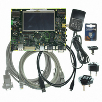
AT91SAM9G45-EKES Atmel, AT91SAM9G45-EKES Datasheet - Page 95

AT91SAM9G45-EKES
Manufacturer Part Number
AT91SAM9G45-EKES
Description
KIT EVAL FOR AT91SAM9G45
Manufacturer
Atmel
Series
AT91SAM Smart ARMr
Type
MCUr
Datasheets
1.AT91SAM9G45-EKES.pdf
(56 pages)
2.AT91SAM9G45-EKES.pdf
(1218 pages)
3.AT91SAM9G45-EKES.pdf
(66 pages)
Specifications of AT91SAM9G45-EKES
Contents
Board
Processor To Be Evaluated
SAM9G45
Data Bus Width
32 bit
Interface Type
I2C, SPI, UART
Maximum Operating Temperature
+ 50 C
Minimum Operating Temperature
- 10 C
Operating Supply Voltage
1.8 V to 3.3 V
For Use With/related Products
AT91SAM9G45
Lead Free Status / RoHS Status
Lead free / RoHS Compliant
Other names
Q4626953
- Current page: 95 of 1218
- Download datasheet (19Mb)
14.5.4
14.5.5
6438F–ATARM–21-Jun-10
Error Checking
Updating Time/Calendar
Depending on the combination of fields enabled, a large number of possibilities are available to
the user ranging from minutes to 365/366 days.
Verification on user interface data is performed when accessing the century, year, month, date,
day, hours, minutes, seconds and alarms. A check is performed on illegal BCD entries such as
illegal date of the month with regard to the year and century configured.
If one of the time fields is not correct, the data is not loaded into the register/counter and a flag is
set in the validity register. The user can not reset this flag. It is reset as soon as an acceptable
value is programmed. This avoids any further side effects in the hardware. The same procedure
is done for the alarm.
The following checks are performed:
Note:
To update any of the time/calendar fields, the user must first stop the RTC by setting the corre-
sponding field in the Control Register. Bit UPDTIM must be set to update time fields (hour,
minute, second) and bit UPDCAL must be set to update calendar fields (century, year, month,
date, day).
Then the user must poll or wait for the interrupt (if enabled) of bit ACKUPD in the Status Regis-
ter. Once the bit reads 1, it is mandatory to clear this flag by writing the corresponding bit in
RTC_SCCR. The user can now write to the appropriate Time and Calendar register.
Once the update is finished, the user must reset (0) UPDTIM and/or UPDCAL in the Control
When entering programming mode of the calendar fields, the time fields remain enabled. When
entering the programming mode of the time fields, both time and calendar fields are stopped.
This is due to the location of the calendar logic circuity (downstream for low-power consider-
ations). It is highly recommended to prepare all the fields to be updated before entering
programming mode. In successive update operations, the user must wait at least one second
after resetting the UPDTIM/UPDCAL bit in the RTC_CR (Control Register) before setting these
bits again. This is done by waiting for the SEC flag in the Status Register before setting
UPDTIM/UPDCAL bit. After resetting UPDTIM/UPDCAL, the SEC flag must also be cleared.
1. Century (check if it is in range 19 - 20)
2. Year (BCD entry check)
3. Date (check range 01 - 31)
4. Month (check if it is in BCD range 01 - 12, check validity regarding “date”)
5. Day (check range 1 - 7)
6. Hour (BCD checks: in 24-hour mode, check range 00 - 23 and check that AM/PM flag is
7. Minute (check BCD and range 00 - 59)
8. Second (check BCD and range 00 - 59)
not set if RTC is set in 24-hour mode; in 12-hour mode check range 01 - 12)
If the 12-hour mode is selected by means of the RTC_MODE register, a 12-hour value can be pro-
grammed and the returned value on RTC_TIME will be the corresponding 24-hour value. The
entry control checks the value of the AM/PM indicator (bit 22 of RTC_TIME register) to determine
the range to be checked.
AT91SAM9G45
95
Related parts for AT91SAM9G45-EKES
Image
Part Number
Description
Manufacturer
Datasheet
Request
R

Part Number:
Description:
MCU ARM9 64K SRAM 144-LFBGA
Manufacturer:
Atmel
Datasheet:

Part Number:
Description:
IC ARM7 MCU FLASH 256K 100LQFP
Manufacturer:
Atmel
Datasheet:

Part Number:
Description:
IC ARM9 MPU 217-LFBGA
Manufacturer:
Atmel
Datasheet:

Part Number:
Description:
MCU ARM9 ULTRA LOW PWR 217-LFBGA
Manufacturer:
Atmel
Datasheet:

Part Number:
Description:
MCU ARM9 324-TFBGA
Manufacturer:
Atmel
Datasheet:

Part Number:
Description:
IC MCU ARM9 SAMPLING 217CBGA
Manufacturer:
Atmel
Datasheet:

Part Number:
Description:
IC ARM9 MCU 217-LFBGA
Manufacturer:
Atmel
Datasheet:

Part Number:
Description:
IC ARM9 MCU 208-PQFP
Manufacturer:
Atmel
Datasheet:

Part Number:
Description:
MCU ARM 512K HS FLASH 100-LQFP
Manufacturer:
Atmel
Datasheet:

Part Number:
Description:
MCU ARM 512K HS FLASH 100-TFBGA
Manufacturer:
Atmel
Datasheet:

Part Number:
Description:
IC ARM9 MCU 200 MHZ 324-TFBGA
Manufacturer:
Atmel
Datasheet:

Part Number:
Description:
IC ARM MCU 16BIT 128K 256BGA
Manufacturer:
Atmel
Datasheet:

Part Number:
Description:
IC ARM7 MCU 32BIT 128K 64LQFP
Manufacturer:
Atmel
Datasheet:

Part Number:
Description:
IC ARM7 MCU FLASH 256K 128-LQFP
Manufacturer:
Atmel
Datasheet:

Part Number:
Description:
IC ARM7 MCU FLASH 512K 128-LQFP
Manufacturer:
Atmel
Datasheet:


