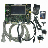
AT91SAM9G45-EKES Atmel, AT91SAM9G45-EKES Datasheet - Page 1169

AT91SAM9G45-EKES
Manufacturer Part Number
AT91SAM9G45-EKES
Description
KIT EVAL FOR AT91SAM9G45
Manufacturer
Atmel
Series
AT91SAM Smart ARMr
Type
MCUr
Datasheets
1.AT91SAM9G45-EKES.pdf
(56 pages)
2.AT91SAM9G45-EKES.pdf
(1218 pages)
3.AT91SAM9G45-EKES.pdf
(66 pages)
Specifications of AT91SAM9G45-EKES
Contents
Board
Processor To Be Evaluated
SAM9G45
Data Bus Width
32 bit
Interface Type
I2C, SPI, UART
Maximum Operating Temperature
+ 50 C
Minimum Operating Temperature
- 10 C
Operating Supply Voltage
1.8 V to 3.3 V
For Use With/related Products
AT91SAM9G45
Lead Free Status / RoHS Status
Lead free / RoHS Compliant
Other names
Q4626953
- Current page: 1169 of 1218
- Download datasheet (19Mb)
46.12 Core Power Supply POR Characteristics
Table 46-25. Power-On-Reset Characteristics
46.12.1
46.12.2
6438F–ATARM–21-Jun-10
Symbol
V
V
T
th+
th-
RES
Power Sequence Requirements
Power-Up Sequence
Parameter
Threshold Voltage Rising
Threshold Voltage Falling
Reset Time
The AT91SAM9G45 board design must comply with the power-up guidelines below to guaran-
tee reliable operation of the device. Any deviation from these sequences may prevent the device
from booting.
Figure 46-2.
VDDCORE and VDDBU are controlled by internal POR (Power-On-Reset) to guarantee that
these power sources reach their target values prior to the release of POR.
• VDDIOP must be
• VDDIOM must reach V
(Tres + T1) after VDDCORE has reached
(Tres +T1 +T2) after VDDCORE has reached
– T
– T1 = 3 x T
– T2 = 16 x T
RES
VDDCOREtyp
Core Supply POR Output
is a POR characteristic
VDDIOtyp
VDD (V)
Conditions
Minimum Slope of +2.0V/30ms
VDDCORE and VDDIO Constraints at Startup
SLCK
Vth+
Voh
Vih
SLCK
SLCK
V
IH
OH
(refer to DC characteristics,
(refer to DC characteristics,
<--- Tres --->
V
th+
.
V
Min
0.5
0.4
30
th+
< T1 >
Table
<------------ T2----------->
Table
46-2, for more details) within
Typ
0.7
0.6
70
46-2, for more details) within
AT91SAM9G45
VDDIO > Vih
VDDIO > Voh
Max
0.89
0.85
130
VDDCORE
VDDIO
t
Units
μs
V
V
1169
Related parts for AT91SAM9G45-EKES
Image
Part Number
Description
Manufacturer
Datasheet
Request
R

Part Number:
Description:
MCU ARM9 64K SRAM 144-LFBGA
Manufacturer:
Atmel
Datasheet:

Part Number:
Description:
IC ARM7 MCU FLASH 256K 100LQFP
Manufacturer:
Atmel
Datasheet:

Part Number:
Description:
IC ARM9 MPU 217-LFBGA
Manufacturer:
Atmel
Datasheet:

Part Number:
Description:
MCU ARM9 ULTRA LOW PWR 217-LFBGA
Manufacturer:
Atmel
Datasheet:

Part Number:
Description:
MCU ARM9 324-TFBGA
Manufacturer:
Atmel
Datasheet:

Part Number:
Description:
IC MCU ARM9 SAMPLING 217CBGA
Manufacturer:
Atmel
Datasheet:

Part Number:
Description:
IC ARM9 MCU 217-LFBGA
Manufacturer:
Atmel
Datasheet:

Part Number:
Description:
IC ARM9 MCU 208-PQFP
Manufacturer:
Atmel
Datasheet:

Part Number:
Description:
MCU ARM 512K HS FLASH 100-LQFP
Manufacturer:
Atmel
Datasheet:

Part Number:
Description:
MCU ARM 512K HS FLASH 100-TFBGA
Manufacturer:
Atmel
Datasheet:

Part Number:
Description:
IC ARM9 MCU 200 MHZ 324-TFBGA
Manufacturer:
Atmel
Datasheet:

Part Number:
Description:
IC ARM MCU 16BIT 128K 256BGA
Manufacturer:
Atmel
Datasheet:

Part Number:
Description:
IC ARM7 MCU 32BIT 128K 64LQFP
Manufacturer:
Atmel
Datasheet:

Part Number:
Description:
IC ARM7 MCU FLASH 256K 128-LQFP
Manufacturer:
Atmel
Datasheet:

Part Number:
Description:
IC ARM7 MCU FLASH 512K 128-LQFP
Manufacturer:
Atmel
Datasheet:


