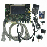
AT91SAM9G45-EKES Atmel, AT91SAM9G45-EKES Datasheet - Page 664

AT91SAM9G45-EKES
Manufacturer Part Number
AT91SAM9G45-EKES
Description
KIT EVAL FOR AT91SAM9G45
Manufacturer
Atmel
Series
AT91SAM Smart ARMr
Type
MCUr
Datasheets
1.AT91SAM9G45-EKES.pdf
(56 pages)
2.AT91SAM9G45-EKES.pdf
(1218 pages)
3.AT91SAM9G45-EKES.pdf
(66 pages)
Specifications of AT91SAM9G45-EKES
Contents
Board
Processor To Be Evaluated
SAM9G45
Data Bus Width
32 bit
Interface Type
I2C, SPI, UART
Maximum Operating Temperature
+ 50 C
Minimum Operating Temperature
- 10 C
Operating Supply Voltage
1.8 V to 3.3 V
For Use With/related Products
AT91SAM9G45
Lead Free Status / RoHS Status
Lead free / RoHS Compliant
Other names
Q4626953
- Current page: 664 of 1218
- Download datasheet (19Mb)
34.5
Table 34-1.
34.6
34.6.1
34.6.2
34.6.3
664
Pin Name
RF
RK
RD
TF
TK
TD
Pin Name List
Product Dependencies
AT91SAM9G45
I/O Lines
Power Management
Interrupt
I/O Lines Description
The pins used for interfacing the compliant external devices may be multiplexed with PIO lines.
Before using the SSC receiver, the PIO controller must be configured to dedicate the SSC
receiver I/O lines to the SSC peripheral mode.
Before using the SSC transmitter, the PIO controller must be configured to dedicate the SSC
transmitter I/O lines to the SSC peripheral mode.
Table 34-2.
The SSC is not continuously clocked. The SSC interface may be clocked through the Power
Management Controller (PMC), therefore the programmer must first configure the PMC to
enable the SSC clock.
The SSC interface has an interrupt line connected to the Advanced Interrupt Controller (AIC).
Handling interrupts requires programming the AICbefore configuring the SSC.
Instance
Pin Description
Receiver Frame Synchro
Receiver Clock
Receiver Data
Transmitter Frame Synchro
Transmitter Clock
Transmitter Data
SSC0
SSC0
SSC0
SSC0
SSC0
SSC0
SSC1
SSC1
SSC1
SSC1
SSC1
SSC1
I/O Lines
Signal
RD0
RK0
RD1
RK1
RF0
TD0
TK0
RF1
TD1
TF1
TK1
TF0
I/O Line
PD11
PD15
PD13
PD10
PD14
PD12
PD3
PD5
PD4
PD2
PD1
PD0
Peripheral
Input/Output
Input/Output
Input/Output
Input/Output
6438F–ATARM–21-Jun-10
Output
Type
Input
A
A
A
A
A
A
A
A
A
A
A
A
Related parts for AT91SAM9G45-EKES
Image
Part Number
Description
Manufacturer
Datasheet
Request
R

Part Number:
Description:
MCU ARM9 64K SRAM 144-LFBGA
Manufacturer:
Atmel
Datasheet:

Part Number:
Description:
IC ARM7 MCU FLASH 256K 100LQFP
Manufacturer:
Atmel
Datasheet:

Part Number:
Description:
IC ARM9 MPU 217-LFBGA
Manufacturer:
Atmel
Datasheet:

Part Number:
Description:
MCU ARM9 ULTRA LOW PWR 217-LFBGA
Manufacturer:
Atmel
Datasheet:

Part Number:
Description:
MCU ARM9 324-TFBGA
Manufacturer:
Atmel
Datasheet:

Part Number:
Description:
IC MCU ARM9 SAMPLING 217CBGA
Manufacturer:
Atmel
Datasheet:

Part Number:
Description:
IC ARM9 MCU 217-LFBGA
Manufacturer:
Atmel
Datasheet:

Part Number:
Description:
IC ARM9 MCU 208-PQFP
Manufacturer:
Atmel
Datasheet:

Part Number:
Description:
MCU ARM 512K HS FLASH 100-LQFP
Manufacturer:
Atmel
Datasheet:

Part Number:
Description:
MCU ARM 512K HS FLASH 100-TFBGA
Manufacturer:
Atmel
Datasheet:

Part Number:
Description:
IC ARM9 MCU 200 MHZ 324-TFBGA
Manufacturer:
Atmel
Datasheet:

Part Number:
Description:
IC ARM MCU 16BIT 128K 256BGA
Manufacturer:
Atmel
Datasheet:

Part Number:
Description:
IC ARM7 MCU 32BIT 128K 64LQFP
Manufacturer:
Atmel
Datasheet:

Part Number:
Description:
IC ARM7 MCU FLASH 256K 128-LQFP
Manufacturer:
Atmel
Datasheet:

Part Number:
Description:
IC ARM7 MCU FLASH 512K 128-LQFP
Manufacturer:
Atmel
Datasheet:


