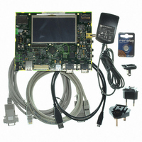
AT91SAM9G45-EKES Atmel, AT91SAM9G45-EKES Datasheet - Page 891

AT91SAM9G45-EKES
Manufacturer Part Number
AT91SAM9G45-EKES
Description
KIT EVAL FOR AT91SAM9G45
Manufacturer
Atmel
Series
AT91SAM Smart ARMr
Type
MCUr
Datasheets
1.AT91SAM9G45-EKES.pdf
(56 pages)
2.AT91SAM9G45-EKES.pdf
(1218 pages)
3.AT91SAM9G45-EKES.pdf
(66 pages)
Specifications of AT91SAM9G45-EKES
Contents
Board
Processor To Be Evaluated
SAM9G45
Data Bus Width
32 bit
Interface Type
I2C, SPI, UART
Maximum Operating Temperature
+ 50 C
Minimum Operating Temperature
- 10 C
Operating Supply Voltage
1.8 V to 3.3 V
For Use With/related Products
AT91SAM9G45
Lead Free Status / RoHS Status
Lead free / RoHS Compliant
Other names
Q4626953
- Current page: 891 of 1218
- Download datasheet (19Mb)
• END_TR_EN: End of Transfer Enable (Control)
Used for OUT transfers only.
0 = USB end of transfer is ignored.
1 = UDPHS device can put an end to the current buffer transfer.
When set, a BULK or INTERRUPT short packet or the last packet of an ISOCHRONOUS (micro) frame (DATAX) will close
the current buffer and the UDPHS_DMASTATUSx register END_TR_ST flag will be raised.
This is intended for UDPHS non-prenegotiated end of transfer (BULK or INTERRUPT) or ISOCHRONOUS microframe
data buffer closure.
• END_B_EN: End of Buffer Enable (Control)
0 = DMA Buffer End has no impact on USB packet transfer.
1 = endpoint can validate the packet (according to the values programmed in the UDPHS_EPTCTLx register AUTO_VALID
and SHRT_PCKT fields) at DMA Buffer End, i.e. when the UDPHS_DMASTATUS register BUFF_COUNT reaches 0.
This is mainly for short packet IN validation initiated by the DMA reaching end of buffer, but could be used for OUT packet
truncation (discarding of unwanted packet data) at the end of DMA buffer.
• END_TR_IT: End of Transfer Interrupt Enable
0 = UDPHS device initiated buffer transfer completion will not trigger any interrupt at UDPHS_STATUSx/END_TR_ST
rising.
1 = an interrupt is sent after the buffer transfer is complete, if the UDPHS device has ended the buffer transfer.
Use when the receive size is unknown.
• END_BUFFIT: End of Buffer Interrupt Enable
0 = UDPHS_DMA_STATUSx/END_BF_ST rising will not trigger any interrupt.
1 = an interrupt is generated when the UDPHS_DMASTATUSx register BUFF_COUNT reaches zero.
• DESC_LD_IT: Descriptor Loaded Interrupt Enable
0 = UDPHS_DMASTATUSx/DESC_LDST rising will not trigger any interrupt.
1 = an interrupt is generated when a descriptor has been loaded from the bus.
• BURST_LCK: Burst Lock Enable
0 = the DMA never locks bus access.
1 = USB packets AHB data bursts are locked for maximum optimization of the bus bandwidth usage and maximization of
fly-by AHB burst duration.
• BUFF_LENGTH: Buffer Byte Length (Write-only)
This field determines the number of bytes to be transferred until end of buffer. The maximum channel transfer size (64
KBytes) is reached when this field is 0 (default value). If the transfer size is unknown, this field should be set to 0, but the
transfer end may occur earlier under UDPHS device control.
When this field is written, The UDPHS_DMASTATUSx register BUFF_COUNT field is updated with the write value.
Note:
Note:
891
Bits [31:2] are only writable when issuing a channel Control Command other than “Stop Now”.
For reliability it is highly recommended to wait for both UDPHS_DMASTATUSx register CHAN_ACT and CHAN_ENB flags are
at 0, thus ensuring the channel has been stopped before issuing a command other than “Stop Now”.
AT91SAM9G45
6438F–ATARM–21-Jun-10
Related parts for AT91SAM9G45-EKES
Image
Part Number
Description
Manufacturer
Datasheet
Request
R

Part Number:
Description:
MCU ARM9 64K SRAM 144-LFBGA
Manufacturer:
Atmel
Datasheet:

Part Number:
Description:
IC ARM7 MCU FLASH 256K 100LQFP
Manufacturer:
Atmel
Datasheet:

Part Number:
Description:
IC ARM9 MPU 217-LFBGA
Manufacturer:
Atmel
Datasheet:

Part Number:
Description:
MCU ARM9 ULTRA LOW PWR 217-LFBGA
Manufacturer:
Atmel
Datasheet:

Part Number:
Description:
MCU ARM9 324-TFBGA
Manufacturer:
Atmel
Datasheet:

Part Number:
Description:
IC MCU ARM9 SAMPLING 217CBGA
Manufacturer:
Atmel
Datasheet:

Part Number:
Description:
IC ARM9 MCU 217-LFBGA
Manufacturer:
Atmel
Datasheet:

Part Number:
Description:
IC ARM9 MCU 208-PQFP
Manufacturer:
Atmel
Datasheet:

Part Number:
Description:
MCU ARM 512K HS FLASH 100-LQFP
Manufacturer:
Atmel
Datasheet:

Part Number:
Description:
MCU ARM 512K HS FLASH 100-TFBGA
Manufacturer:
Atmel
Datasheet:

Part Number:
Description:
IC ARM9 MCU 200 MHZ 324-TFBGA
Manufacturer:
Atmel
Datasheet:

Part Number:
Description:
IC ARM MCU 16BIT 128K 256BGA
Manufacturer:
Atmel
Datasheet:

Part Number:
Description:
IC ARM7 MCU 32BIT 128K 64LQFP
Manufacturer:
Atmel
Datasheet:

Part Number:
Description:
IC ARM7 MCU FLASH 256K 128-LQFP
Manufacturer:
Atmel
Datasheet:

Part Number:
Description:
IC ARM7 MCU FLASH 512K 128-LQFP
Manufacturer:
Atmel
Datasheet:


