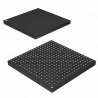
AT91SAM9G45-CU Atmel, AT91SAM9G45-CU Datasheet - Page 137

AT91SAM9G45-CU
Manufacturer Part Number
AT91SAM9G45-CU
Description
MCU ARM9 324-TFBGA
Manufacturer
Atmel
Series
AT91SAMr
Datasheets
1.AT91SAM9G45-EKES.pdf
(56 pages)
2.AT91SAM9G45-EKES.pdf
(1218 pages)
3.AT91SAM9G45-CU.pdf
(10 pages)
Specifications of AT91SAM9G45-CU
Core Processor
ARM9
Core Size
16/32-Bit
Speed
400MHz
Connectivity
EBI/EMI, Ethernet, I²C, IrDA, MMC, SPI, SSC, UART/USART, USB
Peripherals
AC'97, DMA, I²S, LCD, POR, PWM, WDT
Number Of I /o
160
Program Memory Size
64KB (64K x 8)
Program Memory Type
ROM
Ram Size
128K x 8
Voltage - Supply (vcc/vdd)
0.9 V ~ 1.1 V
Data Converters
A/D 8x10b
Oscillator Type
Internal
Operating Temperature
-40°C ~ 85°C
Package / Case
324-TFBGA
Processor Series
AT91SAMx
Core
ARM926EJ-S
Data Bus Width
32 bit
Data Ram Size
64 KB
Interface Type
I2C, SPI, UART
Maximum Clock Frequency
800 MHz
Number Of Programmable I/os
160
Number Of Timers
5
Maximum Operating Temperature
+ 85 C
Mounting Style
SMD/SMT
3rd Party Development Tools
JTRACE-ARM-2M, MDK-ARM, RL-ARM, ULINK2
Development Tools By Supplier
AT91SAM-ICE, AT91-ISP
Minimum Operating Temperature
- 40 C
On-chip Adc
10 bit
Controller Family/series
AT91
No. Of I/o's
160
Ram Memory Size
64KB
Cpu Speed
400MHz
No. Of Timers
2
Rohs Compliant
Yes
For Use With
AT91SAM9G45-EKES - KIT EVAL FOR AT91SAM9G45
Lead Free Status / RoHS Status
Lead free / RoHS Compliant
Eeprom Size
-
Lead Free Status / Rohs Status
Lead free / RoHS Compliant
Available stocks
Company
Part Number
Manufacturer
Quantity
Price
Company:
Part Number:
AT91SAM9G45-CU
Manufacturer:
ATMEL
Quantity:
1 000
Company:
Part Number:
AT91SAM9G45-CU
Manufacturer:
Atmel
Quantity:
31
Part Number:
AT91SAM9G45-CU
Manufacturer:
ATMEL/爱特梅尔
Quantity:
20 000
- Current page: 137 of 1218
- Download datasheet (19Mb)
19.5.1.2
19.5.2
6438F–ATARM–21-Jun-10
Arbitration Priority Scheme
Slot Cycle Limit Arbitration
Use of undefined length 16-beat bursts or less is discouraged since this generally decreases
significantly overall bus bandwidth due to arbitration and slave latencies at each first access of a
burst.
If the master does not permanently and continuously request the same slave or has an intrinsi-
cally limited average throughput, the ULBT should be let at its default unlimited value, knowing
that the AHB specification natively limits all word bursts to 256 beats and double-word bursts to
128 beats because of its 1 Kilobyte address boundaries.
Unless duly needed the ULBT should be let to its default 0 value for power saving.
This selection can be done through the field ULBT of the Master Configuration Registers
(MATRIX_MCFG).
The Bus Matrix contains specific logic to break long accesses, such as back to back undefined
length bursts or very long bursts on a very slow slave (e.g., an external low speed memory). At
each arbitration time a counter is loaded with the value previously written in the SLOT_CYCLE
field of the related Slave Configuration Register (MATRIX_SCFG) and decreased at each clock
cycle. When the counter elapses, the arbiter has the ability to re-arbitrate at the end of the cur-
rent AHB bus access cycle.
Unless some master has a very tight access latency constraint which could lead to data overflow
or underflow due to a badly undersized internal fifo with respect to its throughput, the Slot Cycle
Limit should be disabled (SLOT_CYCLE = 0) or let to its default maximum value in order not to
inefficiently break long bursts performed by some ATMEL masters.
However, the Slot Cycle Limit should not be disabled in the very particular case of a master
capable of accessing the slave by performing back to back undefined length bursts shorter than
the number of ULBT beats with no Idle cycle in between, since in this case the arbitration could
be frozen all along the bursts sequence.
In most cases this feature is not needed and should be disabled for power saving.
Warning: This feature cannot prevent any slave from locking its access indefinitely.
The bus Matrix arbitration scheme is organized in priority pools.
Round-Robin priority is used inside the highest and lowest priority pools, whereas fix level prior-
ity is used between priority pools and inside the intermediate priority pools.
4. 8-beat bursts: Predicted end of burst is generated at the end of each 8-beat boundary
5. 16-beat bursts: Predicted end of burst is generated at the end of each 16-beat bound-
6. 32-beat bursts: Predicted end of burst is generated at the end of each 32-beat bound-
7. 64-beat bursts: Predicted end of burst is generated at the end of each 64-beat bound-
8. 128-beat bursts: Predicted end of burst is generated at the end of each 128-beat
inside INCR transfer.
ary inside INCR transfer.
ary inside INCR transfer.
ary inside INCR transfer.
boundary inside INCR transfer.
AT91SAM9G45
137
Related parts for AT91SAM9G45-CU
Image
Part Number
Description
Manufacturer
Datasheet
Request
R

Part Number:
Description:
MCU, MPU & DSP Development Tools KICKSTART KIT FOR AT91SAM9 PLUS
Manufacturer:
IAR Systems

Part Number:
Description:
DEV KIT FOR AVR/AVR32
Manufacturer:
Atmel
Datasheet:

Part Number:
Description:
INTERVAL AND WIPE/WASH WIPER CONTROL IC WITH DELAY
Manufacturer:
ATMEL Corporation
Datasheet:

Part Number:
Description:
Low-Voltage Voice-Switched IC for Hands-Free Operation
Manufacturer:
ATMEL Corporation
Datasheet:

Part Number:
Description:
MONOLITHIC INTEGRATED FEATUREPHONE CIRCUIT
Manufacturer:
ATMEL Corporation
Datasheet:

Part Number:
Description:
AM-FM Receiver IC U4255BM-M
Manufacturer:
ATMEL Corporation
Datasheet:

Part Number:
Description:
Monolithic Integrated Feature Phone Circuit
Manufacturer:
ATMEL Corporation
Datasheet:

Part Number:
Description:
Multistandard Video-IF and Quasi Parallel Sound Processing
Manufacturer:
ATMEL Corporation
Datasheet:

Part Number:
Description:
High-performance EE PLD
Manufacturer:
ATMEL Corporation
Datasheet:

Part Number:
Description:
8-bit Flash Microcontroller
Manufacturer:
ATMEL Corporation
Datasheet:

Part Number:
Description:
2-Wire Serial EEPROM
Manufacturer:
ATMEL Corporation
Datasheet:


