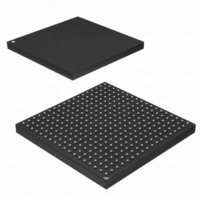
AT91SAM9G45-CU Atmel, AT91SAM9G45-CU Datasheet - Page 850

AT91SAM9G45-CU
Manufacturer Part Number
AT91SAM9G45-CU
Description
MCU ARM9 324-TFBGA
Manufacturer
Atmel
Series
AT91SAMr
Datasheets
1.AT91SAM9G45-EKES.pdf
(56 pages)
2.AT91SAM9G45-EKES.pdf
(1218 pages)
3.AT91SAM9G45-CU.pdf
(10 pages)
Specifications of AT91SAM9G45-CU
Core Processor
ARM9
Core Size
16/32-Bit
Speed
400MHz
Connectivity
EBI/EMI, Ethernet, I²C, IrDA, MMC, SPI, SSC, UART/USART, USB
Peripherals
AC'97, DMA, I²S, LCD, POR, PWM, WDT
Number Of I /o
160
Program Memory Size
64KB (64K x 8)
Program Memory Type
ROM
Ram Size
128K x 8
Voltage - Supply (vcc/vdd)
0.9 V ~ 1.1 V
Data Converters
A/D 8x10b
Oscillator Type
Internal
Operating Temperature
-40°C ~ 85°C
Package / Case
324-TFBGA
Processor Series
AT91SAMx
Core
ARM926EJ-S
Data Bus Width
32 bit
Data Ram Size
64 KB
Interface Type
I2C, SPI, UART
Maximum Clock Frequency
800 MHz
Number Of Programmable I/os
160
Number Of Timers
5
Maximum Operating Temperature
+ 85 C
Mounting Style
SMD/SMT
3rd Party Development Tools
JTRACE-ARM-2M, MDK-ARM, RL-ARM, ULINK2
Development Tools By Supplier
AT91SAM-ICE, AT91-ISP
Minimum Operating Temperature
- 40 C
On-chip Adc
10 bit
Controller Family/series
AT91
No. Of I/o's
160
Ram Memory Size
64KB
Cpu Speed
400MHz
No. Of Timers
2
Rohs Compliant
Yes
For Use With
AT91SAM9G45-EKES - KIT EVAL FOR AT91SAM9G45
Lead Free Status / RoHS Status
Lead free / RoHS Compliant
Eeprom Size
-
Lead Free Status / Rohs Status
Lead free / RoHS Compliant
Available stocks
Company
Part Number
Manufacturer
Quantity
Price
Company:
Part Number:
AT91SAM9G45-CU
Manufacturer:
ATMEL
Quantity:
1 000
Company:
Part Number:
AT91SAM9G45-CU
Manufacturer:
Atmel
Quantity:
31
Part Number:
AT91SAM9G45-CU
Manufacturer:
ATMEL/爱特梅尔
Quantity:
20 000
- Current page: 850 of 1218
- Download datasheet (19Mb)
38.5.12.2
38.5.12.3
38.5.12.4
38.5.12.5
38.5.12.6
850
AT91SAM9G45
Not Powered State
Entering Attached State
From Powered State to Default State (Reset)
From Default State to Address State (Address Assigned)
From Address State to Configured State (Device Configured)
Self powered devices can detect 5V VBUS using a PIO. When the device is not connected to a
host, device power consumption can be reduced by the DETACH bit in UDPHS_CTRL. Dis-
abling the transceiver is automatically done. HSDM, HSDP, FSDP and FSDP lines are tied to
GND pull-downs integrated in the hub downstream ports.
When no device is connected, the USB FSDP and FSDM signals are tied to GND by 15 K pull-
downs integrated in the hub downstream ports. When a device is attached to an hub down-
stream port, the device connects a 1.5 K
state, FSDP is pulled-up by the device 1.5 K
15 K resistor to GND of the host.
After pull-up connection, the device enters the powered state. The transceiver remains disabled
until bus activity is detected.
In case of low power consumption need, the device can be stopped. When the device detects
the VBUS, the software must enable the USB transceiver by enabling the EN_UDPHS bit in
UDPHS_CTRL register.
The software can detach the pull-up by setting DETACH bit in UDPHS_CTRL register.
After its connection to a USB host, the USB device waits for an end-of-bus reset. The unmasked
flag ENDRESET is set in the UDPHS_IEN register and an interrupt is triggered.
Once the ENDRESET interrupt has been triggered, the device enters Default State. In this state,
the UDPHS software must:
In this state, the EN_UDPHS bit in UDPHS_CTRL register must be enabled.
After a Set Address standard device request, the USB host peripheral enters the address state.
Warning: before the device enters address state, it must achieve the Status IN transaction of
the control transfer, i.e., the UDPHS device sets its new address once the TX_COMPLT flag in
the UDPHS_EPTCTL[0] register has been received and cleared.
To move to address state, the driver software sets the DEV_ADDR field and the FADDR_EN
flag in the UDPHS_CTRL register.
Once a valid Set Configuration standard request has been received and acknowledged, the
device enables endpoints corresponding to the current configuration. This is done by setting the
BK_NUMBER, EPT_TYPE, EPT_DIR and EPT_SIZE fields in the UDPHS_EPTCFGx registers
and enabling them by setting the EPT_ENABL flag in the UDPHS_EPTCTLENBx registers, and,
optionally, enabling corresponding interrupts in the UDPHS_IEN register.
• Enable the default endpoint, setting the EPT_ENABL flag in the UDPHS_EPTCTLENB[0]
• Configure the Interrupt Mask Register which has been reset by the USB reset detection
• Enable the transceiver.
register and, optionally, enabling the interrupt for endpoint 0 by writing 1 in EPT_0 of the
UDPHS_IEN register. The enumeration then begins by a control transfer.
pull-up on FSDP. The USB bus line goes into IDLE
resistor to 3.3V and FSDM is pulled-down by the
6438F–ATARM–21-Jun-10
Related parts for AT91SAM9G45-CU
Image
Part Number
Description
Manufacturer
Datasheet
Request
R

Part Number:
Description:
MCU, MPU & DSP Development Tools KICKSTART KIT FOR AT91SAM9 PLUS
Manufacturer:
IAR Systems

Part Number:
Description:
DEV KIT FOR AVR/AVR32
Manufacturer:
Atmel
Datasheet:

Part Number:
Description:
INTERVAL AND WIPE/WASH WIPER CONTROL IC WITH DELAY
Manufacturer:
ATMEL Corporation
Datasheet:

Part Number:
Description:
Low-Voltage Voice-Switched IC for Hands-Free Operation
Manufacturer:
ATMEL Corporation
Datasheet:

Part Number:
Description:
MONOLITHIC INTEGRATED FEATUREPHONE CIRCUIT
Manufacturer:
ATMEL Corporation
Datasheet:

Part Number:
Description:
AM-FM Receiver IC U4255BM-M
Manufacturer:
ATMEL Corporation
Datasheet:

Part Number:
Description:
Monolithic Integrated Feature Phone Circuit
Manufacturer:
ATMEL Corporation
Datasheet:

Part Number:
Description:
Multistandard Video-IF and Quasi Parallel Sound Processing
Manufacturer:
ATMEL Corporation
Datasheet:

Part Number:
Description:
High-performance EE PLD
Manufacturer:
ATMEL Corporation
Datasheet:

Part Number:
Description:
8-bit Flash Microcontroller
Manufacturer:
ATMEL Corporation
Datasheet:

Part Number:
Description:
2-Wire Serial EEPROM
Manufacturer:
ATMEL Corporation
Datasheet:


