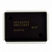
DF2437FV Renesas Electronics America, DF2437FV Datasheet - Page 23

DF2437FV
Manufacturer Part Number
DF2437FV
Description
IC H8S/2437 MCU FLASH 128QFP
Manufacturer
Renesas Electronics America
Series
H8® H8S/2400r
Specifications of DF2437FV
Core Processor
H8S/2600
Core Size
16-Bit
Speed
20MHz
Connectivity
I²C, SCI
Peripherals
POR, PWM, WDT
Number Of I /o
85
Program Memory Size
256KB (256K x 8)
Program Memory Type
FLASH
Ram Size
16K x 8
Voltage - Supply (vcc/vdd)
3 V ~ 3.6 V
Data Converters
A/D 16x10b
Oscillator Type
Internal
Operating Temperature
-20°C ~ 75°C
Package / Case
128-QFP
Lead Free Status / RoHS Status
Lead free / RoHS Compliant
Eeprom Size
-
Available stocks
Company
Part Number
Manufacturer
Quantity
Price
Company:
Part Number:
DF2437FV
Manufacturer:
Renesas Electronics America
Quantity:
10 000
- Current page: 23 of 776
- Download datasheet (5Mb)
21.3 Duty Adjustment Circuit ...................................................................................................643
21.4 Divider ..............................................................................................................................643
21.5 Usage Notes ......................................................................................................................644
Section 22 Power-Down Modes ....................................................................... 645
22.1 Register Descriptions ........................................................................................................648
22.2 Operation...........................................................................................................................652
22.3 φ Clock Output Control.....................................................................................................658
22.4 Usage Notes ......................................................................................................................659
Section 23 List of Registers .............................................................................. 661
23.1 Register Addresses (Address Order) .................................................................................662
23.2 Register Bits......................................................................................................................674
23.3 Register States in Each Operating Mode...........................................................................686
Section 24 Electrical Characteristics ................................................................ 697
24.1 Absolute Maximum Ratings .............................................................................................697
24.2 DC Characteristics ............................................................................................................698
24.3 AC Characteristics ............................................................................................................701
21.2.1 Connecting Crystal Resonator .............................................................................640
21.2.2 External Clock Input Method...............................................................................641
21.5.1 Note on Resonator................................................................................................644
21.5.2 Notes on Board Design ........................................................................................644
21.5.3 Notes on Operation Confirmation........................................................................644
22.1.1 Standby Control Register (SBYCR) ....................................................................648
22.1.2 Module Stop Control Registers H and L (MSTPCRH, MSTPCRL)....................650
22.1.3 Extension Module Stop Control Registers H and L
22.2.1 Clock Division Mode...........................................................................................652
22.2.2 Sleep Mode ..........................................................................................................652
22.2.3 Software Standby Mode.......................................................................................653
22.2.4 Hardware Standby Mode .....................................................................................656
22.2.5 Module Stop Mode ..............................................................................................657
22.4.1 I/O Port State........................................................................................................659
22.4.2 Current Consumption during Oscillation Stabilization Standby Period...............659
22.4.3 On-Chip Peripheral Module Interrupts ................................................................659
22.4.4 Writing to MSTPCR, EXMSTPCR .....................................................................659
22.4.5 Notes on Clock Division Mode............................................................................659
24.3.1 Clock Timing .......................................................................................................701
24.3.2 Control Signal Timing .........................................................................................704
24.3.3 Bus Timing ..........................................................................................................706
24.3.4 Timing of On-Chip Peripheral Modules ..............................................................714
(EXMSTPCRH, EXMSTPCRL)..........................................................................651
Rev.2.00 May. 28, 2009 Page xxi of xxxviii
REJ09B0059-0200
Related parts for DF2437FV
Image
Part Number
Description
Manufacturer
Datasheet
Request
R

Part Number:
Description:
KIT STARTER FOR M16C/29
Manufacturer:
Renesas Electronics America
Datasheet:

Part Number:
Description:
KIT STARTER FOR R8C/2D
Manufacturer:
Renesas Electronics America
Datasheet:

Part Number:
Description:
R0K33062P STARTER KIT
Manufacturer:
Renesas Electronics America
Datasheet:

Part Number:
Description:
KIT STARTER FOR R8C/23 E8A
Manufacturer:
Renesas Electronics America
Datasheet:

Part Number:
Description:
KIT STARTER FOR R8C/25
Manufacturer:
Renesas Electronics America
Datasheet:

Part Number:
Description:
KIT STARTER H8S2456 SHARPE DSPLY
Manufacturer:
Renesas Electronics America
Datasheet:

Part Number:
Description:
KIT STARTER FOR R8C38C
Manufacturer:
Renesas Electronics America
Datasheet:

Part Number:
Description:
KIT STARTER FOR R8C35C
Manufacturer:
Renesas Electronics America
Datasheet:

Part Number:
Description:
KIT STARTER FOR R8CL3AC+LCD APPS
Manufacturer:
Renesas Electronics America
Datasheet:

Part Number:
Description:
KIT STARTER FOR RX610
Manufacturer:
Renesas Electronics America
Datasheet:

Part Number:
Description:
KIT STARTER FOR R32C/118
Manufacturer:
Renesas Electronics America
Datasheet:

Part Number:
Description:
KIT DEV RSK-R8C/26-29
Manufacturer:
Renesas Electronics America
Datasheet:

Part Number:
Description:
KIT STARTER FOR SH7124
Manufacturer:
Renesas Electronics America
Datasheet:

Part Number:
Description:
KIT STARTER FOR H8SX/1622
Manufacturer:
Renesas Electronics America
Datasheet:

Part Number:
Description:
KIT DEV FOR SH7203
Manufacturer:
Renesas Electronics America
Datasheet:


