DF2437FV Renesas Electronics America, DF2437FV Datasheet - Page 38
DF2437FV
Manufacturer Part Number
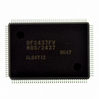
DF2437FV
Description
IC H8S/2437 MCU FLASH 128QFP
Manufacturer
Renesas Electronics America
Series
H8® H8S/2400r
Specifications of DF2437FV
Core Processor
H8S/2600
Core Size
16-Bit
Speed
20MHz
Connectivity
I²C, SCI
Peripherals
POR, PWM, WDT
Number Of I /o
85
Program Memory Size
256KB (256K x 8)
Program Memory Type
FLASH
Ram Size
16K x 8
Voltage - Supply (vcc/vdd)
3 V ~ 3.6 V
Data Converters
A/D 16x10b
Oscillator Type
Internal
Operating Temperature
-20°C ~ 75°C
Package / Case
128-QFP
Lead Free Status / RoHS Status
Lead free / RoHS Compliant
Eeprom Size
-
Available stocks
Company
Part Number
Manufacturer
Quantity
Price
Company:

Part Number:
DF2437FV
Manufacturer:
Renesas Electronics America
Quantity:
10 000


Table 13.12
Section 14 Duty Measurement Circuit
Table 14.1
Table 14.2
Table 14.3
Table 14.4
Section 15 Watchdog Timer (WDT)
Table 15.1
Section 16 Serial Communication Interface (SCI)
Table 16.1
Table 16.2
Table 16.3
Table 16.3
Table 16.3
Table 16.4
Table 16.5
Table 16.6
Table 16.7
Table 16.8
Table 16.9
Table 16.10
Section 17 I
Table 17.1
Table 17.2
Table 17.3
Table 17.4
Section 18 A/D Converter
Table 18.1
Table 18.2
Table 18.3
Table 18.4
Table 18.5
Table 18.6
Section 20 Flash Memory (0.18-μm F-ZTAT Version)
Table 20.1
Table 20.2
Table 20.3
Rev.2.00 May. 28, 2009 Page xxxvi of xxxviii
REJ09B0059-0200
2
C Bus Interface 3 (IIC3)
VSYNCO Output Modes ..................................................................................... 415
Pin Configuration................................................................................................. 419
Interrupt Sources for Duty Measurement Circuit................................................. 428
Switching of Internal Clock and TWCNT Operation .......................................... 431
Switching of External Event Signal and Operation of Edge Detection Circuit.... 433
Interrupt Source ................................................................................................... 441
Pin Configuration................................................................................................. 447
Relationships between N Setting in BRR and Bit Rate B.................................... 456
Examples of BRR Settings for Various Bit Rates (Asynchronous Mode) (1) ..... 457
Examples of BRR Settings for Various Bit Rates (Asynchronous Mode) (2) ..... 458
Examples of BRR Settings for Various Bit Rates (Asynchronous Mode) (3) ..... 459
Maximum Bit Rate for Each Operating Frequency (Asynchronous Mode)......... 460
Maximum Bit Rate with External Clock Input (Asynchronous Mode) ............... 460
BRR Settings for Various Bit Rates (Clocked Synchronous Mode).................... 461
Maximum Bit Rate with External Clock Input (Clocked Synchronous Mode) ... 461
Serial Transfer Formats (Asynchronous Mode)................................................... 463
SSR Status Flags and Receive Data Handling ..................................................... 470
SCI Interrupt Sources........................................................................................... 489
Pin Configuration................................................................................................. 500
Transfer Rate........................................................................................................ 502
Interrupt Requests ................................................................................................ 528
Time for Monitoring SCL.................................................................................... 529
Pin Configuration................................................................................................. 533
Analog Input Channels and Corresponding ADDR............................................. 534
A/D Conversion Time (Single Mode).................................................................. 540
A/D Conversion Time (Scan Mode) .................................................................... 541
A/D Converter Interrupt Source........................................................................... 542
Analog Pin Specifications.................................................................................... 546
Comparison of Programming Modes................................................................... 552
Pin Configuration................................................................................................. 557
Registers/Parameters and Target Modes.............................................................. 558
Related parts for DF2437FV
Image
Part Number
Description
Manufacturer
Datasheet
Request
R

Part Number:
Description:
KIT STARTER FOR M16C/29
Manufacturer:
Renesas Electronics America
Datasheet:

Part Number:
Description:
KIT STARTER FOR R8C/2D
Manufacturer:
Renesas Electronics America
Datasheet:

Part Number:
Description:
R0K33062P STARTER KIT
Manufacturer:
Renesas Electronics America
Datasheet:

Part Number:
Description:
KIT STARTER FOR R8C/23 E8A
Manufacturer:
Renesas Electronics America
Datasheet:

Part Number:
Description:
KIT STARTER FOR R8C/25
Manufacturer:
Renesas Electronics America
Datasheet:

Part Number:
Description:
KIT STARTER H8S2456 SHARPE DSPLY
Manufacturer:
Renesas Electronics America
Datasheet:

Part Number:
Description:
KIT STARTER FOR R8C38C
Manufacturer:
Renesas Electronics America
Datasheet:

Part Number:
Description:
KIT STARTER FOR R8C35C
Manufacturer:
Renesas Electronics America
Datasheet:

Part Number:
Description:
KIT STARTER FOR R8CL3AC+LCD APPS
Manufacturer:
Renesas Electronics America
Datasheet:
Part Number:
Description:
KIT STARTER FOR RX610
Manufacturer:
Renesas Electronics America
Datasheet:

Part Number:
Description:
KIT STARTER FOR R32C/118
Manufacturer:
Renesas Electronics America
Datasheet:

Part Number:
Description:
KIT DEV RSK-R8C/26-29
Manufacturer:
Renesas Electronics America
Datasheet:

Part Number:
Description:
KIT STARTER FOR SH7124
Manufacturer:
Renesas Electronics America
Datasheet:

Part Number:
Description:
KIT STARTER FOR H8SX/1622
Manufacturer:
Renesas Electronics America
Datasheet:

Part Number:
Description:
KIT DEV FOR SH7203
Manufacturer:
Renesas Electronics America
Datasheet: