DF2437FV Renesas Electronics America, DF2437FV Datasheet - Page 449
DF2437FV
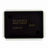
Manufacturer Part Number
DF2437FV
Description
IC H8S/2437 MCU FLASH 128QFP
Manufacturer
Renesas Electronics America
Series
H8® H8S/2400r
Specifications of DF2437FV
Core Processor
H8S/2600
Core Size
16-Bit
Speed
20MHz
Connectivity
I²C, SCI
Peripherals
POR, PWM, WDT
Number Of I /o
85
Program Memory Size
256KB (256K x 8)
Program Memory Type
FLASH
Ram Size
16K x 8
Voltage - Supply (vcc/vdd)
3 V ~ 3.6 V
Data Converters
A/D 16x10b
Oscillator Type
Internal
Operating Temperature
-20°C ~ 75°C
Package / Case
128-QFP
Lead Free Status / RoHS Status
Lead free / RoHS Compliant
Eeprom Size
-
Available stocks
Company
Part Number
Manufacturer
Quantity
Price
Company:

Part Number:
DF2437FV
Manufacturer:
Renesas Electronics America
Quantity:
10 000


Section 13 Timer Connection
13.4.6
Internal Synchronization Signal Generation (IHG/IVG/CL4 Signal Generation)
By using the timer connection, FRT, and TMRY, it is possible to automatically generate internal
signals (IHG and IVG signals) corresponding to the IHI and IVI signals. As the IHG signal is
synchronized with the rise of the IVG signal, the IHG signal period must be made a divisor of the
IVG signal period in order to keep it constant. In addition, the CL4 signal can be generated in
synchronization with the IHG signal. Figure 13.14 shows a block diagram for IHG signal
generation and figure 13.15 shows a block diagram for IVG signal generation.
The contents of OCRA of the FRT can be updated by the automatic addition of the contents of
OCRAR or OCRAF, alternately, each time a compare-match occurs. A value corresponding to the
0 interval of the IVG signal is written to OCRAR, and a value corresponding to the 1 interval of
the IVG signal is written to OCRAF. The IVG signal is set by a compare-match after an OCRAR
addition, and reset by a compare-match after an OCRAF addition.
The IHG signal is the TMRY timer output. The TMRY is set to count internal clock pulses, and to
be cleared on a TCORA compare-match, to fix the period and set the timer output. TCORB is set
so as to reset the timer output. The IVG signal is connected as the TMRY reset input (TMRI), and
the rise of the IVG signal can be treated in the same way as a TCORA compare-match.
The CL4 signal is a waveform that rises within one system clock period after the fall of the IHG
signal, and has an interval of 1 for 6 system clock periods.
Examples of TCR, TCSR, TCORA, and TCORB settings of the TMRY, and TCR, OCRAR,
OCRAF, and TOCR settings of the FRT are shown in table 13.10, and the IHG signal and IVG
signal timing chart is shown in figure 13.16.
Rev.2.00 May. 28, 2009 Page 409 of 732
REJ09B0059-0200
Related parts for DF2437FV
Image
Part Number
Description
Manufacturer
Datasheet
Request
R

Part Number:
Description:
KIT STARTER FOR M16C/29
Manufacturer:
Renesas Electronics America
Datasheet:

Part Number:
Description:
KIT STARTER FOR R8C/2D
Manufacturer:
Renesas Electronics America
Datasheet:

Part Number:
Description:
R0K33062P STARTER KIT
Manufacturer:
Renesas Electronics America
Datasheet:

Part Number:
Description:
KIT STARTER FOR R8C/23 E8A
Manufacturer:
Renesas Electronics America
Datasheet:

Part Number:
Description:
KIT STARTER FOR R8C/25
Manufacturer:
Renesas Electronics America
Datasheet:

Part Number:
Description:
KIT STARTER H8S2456 SHARPE DSPLY
Manufacturer:
Renesas Electronics America
Datasheet:

Part Number:
Description:
KIT STARTER FOR R8C38C
Manufacturer:
Renesas Electronics America
Datasheet:

Part Number:
Description:
KIT STARTER FOR R8C35C
Manufacturer:
Renesas Electronics America
Datasheet:

Part Number:
Description:
KIT STARTER FOR R8CL3AC+LCD APPS
Manufacturer:
Renesas Electronics America
Datasheet:
Part Number:
Description:
KIT STARTER FOR RX610
Manufacturer:
Renesas Electronics America
Datasheet:

Part Number:
Description:
KIT STARTER FOR R32C/118
Manufacturer:
Renesas Electronics America
Datasheet:

Part Number:
Description:
KIT DEV RSK-R8C/26-29
Manufacturer:
Renesas Electronics America
Datasheet:

Part Number:
Description:
KIT STARTER FOR SH7124
Manufacturer:
Renesas Electronics America
Datasheet:

Part Number:
Description:
KIT STARTER FOR H8SX/1622
Manufacturer:
Renesas Electronics America
Datasheet:

Part Number:
Description:
KIT DEV FOR SH7203
Manufacturer:
Renesas Electronics America
Datasheet: