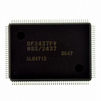
DF2437FV Renesas Electronics America, DF2437FV Datasheet - Page 444

DF2437FV
Manufacturer Part Number
DF2437FV
Description
IC H8S/2437 MCU FLASH 128QFP
Manufacturer
Renesas Electronics America
Series
H8® H8S/2400r
Specifications of DF2437FV
Core Processor
H8S/2600
Core Size
16-Bit
Speed
20MHz
Connectivity
I²C, SCI
Peripherals
POR, PWM, WDT
Number Of I /o
85
Program Memory Size
256KB (256K x 8)
Program Memory Type
FLASH
Ram Size
16K x 8
Voltage - Supply (vcc/vdd)
3 V ~ 3.6 V
Data Converters
A/D 16x10b
Oscillator Type
Internal
Operating Temperature
-20°C ~ 75°C
Package / Case
128-QFP
Lead Free Status / RoHS Status
Lead free / RoHS Compliant
Eeprom Size
-
Available stocks
Company
Part Number
Manufacturer
Quantity
Price
Company:
Part Number:
DF2437FV
Manufacturer:
Renesas Electronics America
Quantity:
10 000
- Current page: 444 of 776
- Download datasheet (5Mb)
13.4.4
By using the timer connection and FRT, even if there is a part of the IHI signal with twice the
frequency, this can be eliminated. In order for this function to operate properly, the duty cycle of
the IHI signal must be approximately 30% or less, or approximately 70% or above.
The 8-bit OCRDM contents or twice the OCRDM contents can be added automatically to the data
captured in ICRD of the FRT, and compare-matches generated at these points. The interval
between the two compare-matches is called a mask interval. A value equivalent to approximately
1/3 the IHI signal period is written to OCRDM. ICRD is set so that capture is performed on the
rise of the IHI signal. Figure 13.10 shows a block diagram for 2fH modification of the IHI signal.
Since the IHI signal supplied to the IHO signal selection circuit is normally set on the rise of the
IHI signal and reset on the fall, its waveform is the same as that of the original IHI signal. When
2fH modification is selected, IHI signal edge detection is disabled during mask intervals. Capture
is also disabled during these intervals.
Examples of TCR, TCSR, TOCR, and OCRDM settings of the FRT are shown in table 13.8, and
the 2fH modification timing chart is shown in figure 13.11.
Rev.2.00 May. 28, 2009 Page 404 of 732
REJ09B0059-0200
2fH Modification of IHI Signal
IVI signal
IHI signal
divided
waveform
Figure 13.9 Timing Chart for Measurement of IVI Signal and
FRC
ICRB
ICRB(1)
IHI Signal Divided Waveform Periods
ICRB(2)
ICRB(3)
ICRB(4)
Related parts for DF2437FV
Image
Part Number
Description
Manufacturer
Datasheet
Request
R

Part Number:
Description:
KIT STARTER FOR M16C/29
Manufacturer:
Renesas Electronics America
Datasheet:

Part Number:
Description:
KIT STARTER FOR R8C/2D
Manufacturer:
Renesas Electronics America
Datasheet:

Part Number:
Description:
R0K33062P STARTER KIT
Manufacturer:
Renesas Electronics America
Datasheet:

Part Number:
Description:
KIT STARTER FOR R8C/23 E8A
Manufacturer:
Renesas Electronics America
Datasheet:

Part Number:
Description:
KIT STARTER FOR R8C/25
Manufacturer:
Renesas Electronics America
Datasheet:

Part Number:
Description:
KIT STARTER H8S2456 SHARPE DSPLY
Manufacturer:
Renesas Electronics America
Datasheet:

Part Number:
Description:
KIT STARTER FOR R8C38C
Manufacturer:
Renesas Electronics America
Datasheet:

Part Number:
Description:
KIT STARTER FOR R8C35C
Manufacturer:
Renesas Electronics America
Datasheet:

Part Number:
Description:
KIT STARTER FOR R8CL3AC+LCD APPS
Manufacturer:
Renesas Electronics America
Datasheet:

Part Number:
Description:
KIT STARTER FOR RX610
Manufacturer:
Renesas Electronics America
Datasheet:

Part Number:
Description:
KIT STARTER FOR R32C/118
Manufacturer:
Renesas Electronics America
Datasheet:

Part Number:
Description:
KIT DEV RSK-R8C/26-29
Manufacturer:
Renesas Electronics America
Datasheet:

Part Number:
Description:
KIT STARTER FOR SH7124
Manufacturer:
Renesas Electronics America
Datasheet:

Part Number:
Description:
KIT STARTER FOR H8SX/1622
Manufacturer:
Renesas Electronics America
Datasheet:

Part Number:
Description:
KIT DEV FOR SH7203
Manufacturer:
Renesas Electronics America
Datasheet:


