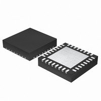
EFM32G200F16 Energy Micro, EFM32G200F16 Datasheet - Page 136

EFM32G200F16
Manufacturer Part Number
EFM32G200F16
Description
MCU 32BIT 16KB FLASH 32-QFN
Manufacturer
Energy Micro
Series
Geckor
Datasheets
1.EFM32G200F16.pdf
(63 pages)
2.EFM32G200F16.pdf
(10 pages)
3.EFM32G200F16.pdf
(463 pages)
4.EFM32G200F16.pdf
(136 pages)
Specifications of EFM32G200F16
Core Processor
ARM® Cortex-M3™
Core Size
32-Bit
Speed
32MHz
Connectivity
EBI/EMI, I²C, IrDA, SmartCard, SPI, UART/USART
Peripherals
Brown-out Detect/Reset, DMA, POR, PWM, WDT
Number Of I /o
24
Program Memory Size
16KB (16K x 8)
Program Memory Type
FLASH
Ram Size
8K x 8
Voltage - Supply (vcc/vdd)
1.8 V ~ 3.8 V
Data Converters
A/D 4x12b, D/A 1x12b
Oscillator Type
External
Operating Temperature
-40°C ~ 85°C
Package / Case
32-VQFN Exposed Pad
Processor Series
EFM32G200
Core
ARM Cortex-M3
Data Bus Width
32 bit
Data Ram Size
8 KB
Interface Type
I2C, UART
Maximum Clock Frequency
32 MHz
Number Of Programmable I/os
24
Number Of Timers
2
Operating Supply Voltage
1.8 V to 3.8 V
Maximum Operating Temperature
+ 85 C
Mounting Style
SMD/SMT
Minimum Operating Temperature
- 40 C
Lead Free Status / RoHS Status
Lead free / RoHS Compliant
Eeprom Size
-
Lead Free Status / Rohs Status
Details
- EFM32G200F16 PDF datasheet
- EFM32G200F16 PDF datasheet #2
- EFM32G200F16 PDF datasheet #3
- EFM32G200F16 PDF datasheet #4
- Current page: 136 of 463
- Download datasheet (8Mb)
14.3.5 Data Access Width
14.3.6 Bank Access
14.3.7 WAIT/ARDY.
2010-09-06 - d0001_Rev1.00
Table 14.1. EBI Timing
It is important that the setting of the data width of the external device is respected. If the size of a request
does not match the data width specified in the MODE register, a bus fault is generated.
The EBI is split in 4 different address regions, each connected to an individual EBI_CSn line. When
accessing one of the memory regions, the corresponding CSn line is asserted. This way up to 4 separate
devices can share the EBI lines and be identified by the EBI_CSn line. Each bank can individually be
enabled or disabled in the EBI_CTRL register. The bank separation is 64 MB. Refer to the memory map
of the EFM32G for a more detailed specification on the memory locations available.
Some external devices are able to indicate that they are not finished with either write or read operation
by asserting the WAIT / ARDY line. This input signal is used to extend the REn/WEn cycles. The ARDY
Reference
t
t
t
t
t
t
t
t
t
t
t
t
t
t
t
t
ALS
ALH
ALW
ARS
ARH
RW
DRS
DRH
AWS
AWH
DWS
DWH
WW
CH
CRS
CWS
Parameter
Address Setup
before ALE high
Address Hold after
ALE high
ALE Width
Address Setup
before RE high
Address Hold after
RE high
Data Read Strobe
Width
Data Setup before
RE high
Data Hold after RE
high
Address Setup
before WE low
Address Hold after
WE high
Data Setup before
WE high
Data Hold after
WE high
Data Write Strobe
Width
Chip Select Hold
after WE / RE high
Chip Select Setup
to RE low
Chip Select Setup
to WE low
Min
0
...the world's most energy friendly microcontrollers
136
Typical
50
1
1
1
1
1
1
1
1
1
1
1
1
0
1
Max
www.energymicro.com
Unit
t
t
t
t
t
t
ns
ns
t
t
t
t
t
t
t
t
CORE_PERIOD
CORE_PERIOD
CORE_PERIOD
CORE_PERIOD
CORE_PERIOD
CORE_PERIOD
CORE_PERIOD
CORE_PERIOD
CORE_PERIOD
CORE_PERIOD
CORE_PERIOD
CORE_PERIOD
CORE_PERIOD
CORE_PERIOD
Related parts for EFM32G200F16
Image
Part Number
Description
Manufacturer
Datasheet
Request
R

Part Number:
Description:
KIT STARTER EFM32 GECKO
Manufacturer:
Energy Micro
Datasheet:

Part Number:
Description:
KIT DEV EFM32 GECKO LCD SUPPORT
Manufacturer:
Energy Micro
Datasheet:

Part Number:
Description:
BOARD PROTOTYPING FOR EFM32
Manufacturer:
Energy Micro
Datasheet:

Part Number:
Description:
KIT DEVELOPMENT EFM32 GECKO
Manufacturer:
Energy Micro
Datasheet:

Part Number:
Description:
MCU, MPU & DSP Development Tools TG840 Sample Kit
Manufacturer:
Energy Micro
Datasheet:

Part Number:
Description:
MCU, MPU & DSP Development Tools TG Starter Kit
Manufacturer:
Energy Micro
Datasheet:

Part Number:
Description:
MCU, MPU & DSP Development Tools TG108 Sample Kit
Manufacturer:
Energy Micro

Part Number:
Description:
MCU, MPU & DSP Development Tools TG210 Sample Kit
Manufacturer:
Energy Micro
Datasheet:

Part Number:
Description:
MCU, MPU & DSP Development Tools TG822 Sample Kit
Manufacturer:
Energy Micro
Datasheet:

Part Number:
Description:
MCU, MPU & DSP Development Tools TG230 Sample Kit
Manufacturer:
Energy Micro

Part Number:
Description:
SAMPLE KIT (SMALL BOX - CONTAINING 2 DEVICES)
Manufacturer:
Energy Micro

Part Number:
Description:
SAMPLE KIT (SMALL BOX - CONTAINING 2 DEVICES)
Manufacturer:
Energy Micro


