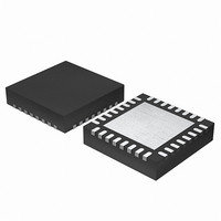
EFM32G200F16 Energy Micro, EFM32G200F16 Datasheet - Page 310

EFM32G200F16
Manufacturer Part Number
EFM32G200F16
Description
MCU 32BIT 16KB FLASH 32-QFN
Manufacturer
Energy Micro
Series
Geckor
Datasheets
1.EFM32G200F16.pdf
(63 pages)
2.EFM32G200F16.pdf
(10 pages)
3.EFM32G200F16.pdf
(463 pages)
4.EFM32G200F16.pdf
(136 pages)
Specifications of EFM32G200F16
Core Processor
ARM® Cortex-M3™
Core Size
32-Bit
Speed
32MHz
Connectivity
EBI/EMI, I²C, IrDA, SmartCard, SPI, UART/USART
Peripherals
Brown-out Detect/Reset, DMA, POR, PWM, WDT
Number Of I /o
24
Program Memory Size
16KB (16K x 8)
Program Memory Type
FLASH
Ram Size
8K x 8
Voltage - Supply (vcc/vdd)
1.8 V ~ 3.8 V
Data Converters
A/D 4x12b, D/A 1x12b
Oscillator Type
External
Operating Temperature
-40°C ~ 85°C
Package / Case
32-VQFN Exposed Pad
Processor Series
EFM32G200
Core
ARM Cortex-M3
Data Bus Width
32 bit
Data Ram Size
8 KB
Interface Type
I2C, UART
Maximum Clock Frequency
32 MHz
Number Of Programmable I/os
24
Number Of Timers
2
Operating Supply Voltage
1.8 V to 3.8 V
Maximum Operating Temperature
+ 85 C
Mounting Style
SMD/SMT
Minimum Operating Temperature
- 40 C
Lead Free Status / RoHS Status
Lead free / RoHS Compliant
Eeprom Size
-
Lead Free Status / Rohs Status
Details
- EFM32G200F16 PDF datasheet
- EFM32G200F16 PDF datasheet #2
- EFM32G200F16 PDF datasheet #3
- EFM32G200F16 PDF datasheet #4
- Current page: 310 of 463
- Download datasheet (8Mb)
22.3.2 Register Access
22.3.3 Clock Sources
22.3.4 Input Filter
2010-09-06 - d0001_Rev1.00
Table 22.1. PCNT QUAD Mode Counter Control Function
Note
The counter-clock domain may be clocked externally. To update the counter-clock domain registers
from software in this mode, 2-3 clock pulses on the external clock are needed to synchronize accesses
to the externally clocked domain. Clock source switching is controlled from the registers in the CMU
(Chapter 11 (p. 90) ).
When the RSTEN bit in the PCNTn_CTRL register is set to 1, the PCNT clock domain is asynchronously
held in reset. The reset is synchronously released two PCNT clock edges after the RSTEN bit in the
PCNTn_CTRL register is cleared by software. This asynchronous reset restores the reset values in
PCNTn_TOP, PCNTn_CNT and other control registers in the PCNT clock domain.
Note
The 32 kHz LFACLK is one of two possible clock sources. The clock select register is described in
Chapter 11 (p. 90) . The default clock source is the LFACLK.
This PCNT module may also use PCNTn_S0IN as an external clock to clock the counter and to sample
PCNTn_S1IN (EXTCLKSINGLE and EXTCLKQUAD mode). Setup, hold and max frequency constraints
for PCNTn_S0IN and PCNTn_S1IN for these modes are specified in the device datasheet.
To use this module, the LE interface clock must be enabled in CMU_HFCORECLKEN0, in addition to
the module clock.
Note
An optional pulse width filter is available in OVSSINGLE mode. The filter is enabled by writing 1 to the
FILT bit in the PCNTn_CTRL register. When enabled, the high and low periods of PCNTn_S0IN must
be stable for 5 consecutive clock cycles before the edge is passed to the edge detector.
In EXTCLKSINGLE and EXTCLKQUAD mode, there is no digital pulse width filter available.
Inputs
S1IN posedge
0
0
1
1
PCNTn_S1IN is sampled on both edges of PCNTn_S0IN.
PCNTn_TOP and PCNTn_CNT are read-only registers. When writing to PCNTn_TOPB,
make sure that the counter value, PCNTn_CNT, can not exceed the value written to
PCNTn_TOPB within two clock cycles.
PCNT Clock Domain Reset, RSTEN, should be set when changing clock source for PCNT.
If changing to an external clock source, the clock pin has to be enabled as input prior to
deasserting RSTEN. Changing clock source without asserting RSTEN results in undefined
behaviour.
S1IN negedge
0
1
0
1
...the world's most energy friendly microcontrollers
310
Control/Status
Count Enable
0
1
1
0
CNTDIR status bit
0
0
1
0
www.energymicro.com
Related parts for EFM32G200F16
Image
Part Number
Description
Manufacturer
Datasheet
Request
R

Part Number:
Description:
KIT STARTER EFM32 GECKO
Manufacturer:
Energy Micro
Datasheet:

Part Number:
Description:
KIT DEV EFM32 GECKO LCD SUPPORT
Manufacturer:
Energy Micro
Datasheet:

Part Number:
Description:
BOARD PROTOTYPING FOR EFM32
Manufacturer:
Energy Micro
Datasheet:

Part Number:
Description:
KIT DEVELOPMENT EFM32 GECKO
Manufacturer:
Energy Micro
Datasheet:

Part Number:
Description:
MCU, MPU & DSP Development Tools TG840 Sample Kit
Manufacturer:
Energy Micro
Datasheet:

Part Number:
Description:
MCU, MPU & DSP Development Tools TG Starter Kit
Manufacturer:
Energy Micro
Datasheet:

Part Number:
Description:
MCU, MPU & DSP Development Tools TG108 Sample Kit
Manufacturer:
Energy Micro

Part Number:
Description:
MCU, MPU & DSP Development Tools TG210 Sample Kit
Manufacturer:
Energy Micro
Datasheet:

Part Number:
Description:
MCU, MPU & DSP Development Tools TG822 Sample Kit
Manufacturer:
Energy Micro
Datasheet:

Part Number:
Description:
MCU, MPU & DSP Development Tools TG230 Sample Kit
Manufacturer:
Energy Micro

Part Number:
Description:
SAMPLE KIT (SMALL BOX - CONTAINING 2 DEVICES)
Manufacturer:
Energy Micro

Part Number:
Description:
SAMPLE KIT (SMALL BOX - CONTAINING 2 DEVICES)
Manufacturer:
Energy Micro


