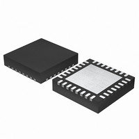
EFM32G200F16 Energy Micro, EFM32G200F16 Datasheet - Page 390

EFM32G200F16
Manufacturer Part Number
EFM32G200F16
Description
MCU 32BIT 16KB FLASH 32-QFN
Manufacturer
Energy Micro
Series
Geckor
Datasheets
1.EFM32G200F16.pdf
(63 pages)
2.EFM32G200F16.pdf
(10 pages)
3.EFM32G200F16.pdf
(463 pages)
4.EFM32G200F16.pdf
(136 pages)
Specifications of EFM32G200F16
Core Processor
ARM® Cortex-M3™
Core Size
32-Bit
Speed
32MHz
Connectivity
EBI/EMI, I²C, IrDA, SmartCard, SPI, UART/USART
Peripherals
Brown-out Detect/Reset, DMA, POR, PWM, WDT
Number Of I /o
24
Program Memory Size
16KB (16K x 8)
Program Memory Type
FLASH
Ram Size
8K x 8
Voltage - Supply (vcc/vdd)
1.8 V ~ 3.8 V
Data Converters
A/D 4x12b, D/A 1x12b
Oscillator Type
External
Operating Temperature
-40°C ~ 85°C
Package / Case
32-VQFN Exposed Pad
Processor Series
EFM32G200
Core
ARM Cortex-M3
Data Bus Width
32 bit
Data Ram Size
8 KB
Interface Type
I2C, UART
Maximum Clock Frequency
32 MHz
Number Of Programmable I/os
24
Number Of Timers
2
Operating Supply Voltage
1.8 V to 3.8 V
Maximum Operating Temperature
+ 85 C
Mounting Style
SMD/SMT
Minimum Operating Temperature
- 40 C
Lead Free Status / RoHS Status
Lead free / RoHS Compliant
Eeprom Size
-
Lead Free Status / Rohs Status
Details
- EFM32G200F16 PDF datasheet
- EFM32G200F16 PDF datasheet #2
- EFM32G200F16 PDF datasheet #3
- EFM32G200F16 PDF datasheet #4
- Current page: 390 of 463
- Download datasheet (8Mb)
28.3 Functional Description
2010-09-06 - d0001_Rev1.00
• Glitch suppression input filter.
• Analog connection to e.g. ADC or LCD.
• Alternate functions (e.g. peripheral outputs and inputs)
• Toggle, set and clear registers for output data
• Dedicated data input register (read-only)
• Interrupts
• Peripheral Reflex System producer
• Configuration lock functionality to avoid accidental changes
An overview of the GPIO module is shown in Figure 28.1 (p. 391) .The GPIO pins are grouped into 16-
pin ports. Each individual GPIO pin is called Pxn where x indicates the port (A, B, C ...) and n indicates
the pin number (0,1,....,15). Fewer than 16 bits may be available on some ports, depending on the total
number of I/O pins on the package. After a reset both input and output is disabled for all pins on the
device, except for debug pins. To use a pin, the port GPIO_Px_MODEL/GPIO_Px_MODEH registers
must be configured for the pin to make it an input or output. These registers can also do more advanced
configuration, which is covered in Section 28.3.1 (p. 391) . When the port is either configured as an
input or an output, the Data In Register (GPIO_Px_DIN) can be used to read the level of each pin in the
port (bit n in the register is connected to pin n on the port). When configured as an output, the value of
the Data Out Register (GPIO_Px_DOUT) will be driven to the pin.
The DOUT value can be changed in 4 different ways
• Writing to the GPIO_Px_DOUT register.
• Writing a 1 to a bit in the GPIO_Px_DOUTSET register sets the corresponding DOUT bit
• Writing a 1 to a bit in the GPIO_Px_DOUTCLR register clears the corresponding DOUT bit
• Writing a 1 to a bit in the GPIO_Px_DOUTTGL register toggles the corresponding DOUT bit
Reading the GPIO_Px_DOUT register will return its contents. Reading the GPIO_Px_DOUTSET,
GPIO_Px_CLR or GPIO_Px_TGL will return 0.
• Routed to several locations on the device
• Pin connections can be enabled individually
• Output data can be overridden by peripheral
• Output enable can be overridden by peripheral
• 2 interrupt lines from up to 16 pending sources
• Separate enable, status, set and clear registers
• Asynchronous sensing
• Rising, falling or both edges
• Wake up from EM0-EM3
• All GPIO pins are selectable
• All GPIO pins are selectable
...the world's most energy friendly microcontrollers
390
www.energymicro.com
Related parts for EFM32G200F16
Image
Part Number
Description
Manufacturer
Datasheet
Request
R

Part Number:
Description:
KIT STARTER EFM32 GECKO
Manufacturer:
Energy Micro
Datasheet:

Part Number:
Description:
KIT DEV EFM32 GECKO LCD SUPPORT
Manufacturer:
Energy Micro
Datasheet:

Part Number:
Description:
BOARD PROTOTYPING FOR EFM32
Manufacturer:
Energy Micro
Datasheet:

Part Number:
Description:
KIT DEVELOPMENT EFM32 GECKO
Manufacturer:
Energy Micro
Datasheet:

Part Number:
Description:
MCU, MPU & DSP Development Tools TG840 Sample Kit
Manufacturer:
Energy Micro
Datasheet:

Part Number:
Description:
MCU, MPU & DSP Development Tools TG Starter Kit
Manufacturer:
Energy Micro
Datasheet:

Part Number:
Description:
MCU, MPU & DSP Development Tools TG108 Sample Kit
Manufacturer:
Energy Micro

Part Number:
Description:
MCU, MPU & DSP Development Tools TG210 Sample Kit
Manufacturer:
Energy Micro
Datasheet:

Part Number:
Description:
MCU, MPU & DSP Development Tools TG822 Sample Kit
Manufacturer:
Energy Micro
Datasheet:

Part Number:
Description:
MCU, MPU & DSP Development Tools TG230 Sample Kit
Manufacturer:
Energy Micro

Part Number:
Description:
SAMPLE KIT (SMALL BOX - CONTAINING 2 DEVICES)
Manufacturer:
Energy Micro

Part Number:
Description:
SAMPLE KIT (SMALL BOX - CONTAINING 2 DEVICES)
Manufacturer:
Energy Micro


