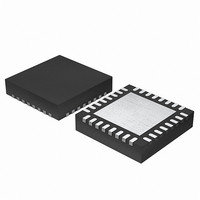
EFM32G200F16 Energy Micro, EFM32G200F16 Datasheet - Page 190

EFM32G200F16
Manufacturer Part Number
EFM32G200F16
Description
MCU 32BIT 16KB FLASH 32-QFN
Manufacturer
Energy Micro
Series
Geckor
Datasheets
1.EFM32G200F16.pdf
(63 pages)
2.EFM32G200F16.pdf
(10 pages)
3.EFM32G200F16.pdf
(463 pages)
4.EFM32G200F16.pdf
(136 pages)
Specifications of EFM32G200F16
Core Processor
ARM® Cortex-M3™
Core Size
32-Bit
Speed
32MHz
Connectivity
EBI/EMI, I²C, IrDA, SmartCard, SPI, UART/USART
Peripherals
Brown-out Detect/Reset, DMA, POR, PWM, WDT
Number Of I /o
24
Program Memory Size
16KB (16K x 8)
Program Memory Type
FLASH
Ram Size
8K x 8
Voltage - Supply (vcc/vdd)
1.8 V ~ 3.8 V
Data Converters
A/D 4x12b, D/A 1x12b
Oscillator Type
External
Operating Temperature
-40°C ~ 85°C
Package / Case
32-VQFN Exposed Pad
Processor Series
EFM32G200
Core
ARM Cortex-M3
Data Bus Width
32 bit
Data Ram Size
8 KB
Interface Type
I2C, UART
Maximum Clock Frequency
32 MHz
Number Of Programmable I/os
24
Number Of Timers
2
Operating Supply Voltage
1.8 V to 3.8 V
Maximum Operating Temperature
+ 85 C
Mounting Style
SMD/SMT
Minimum Operating Temperature
- 40 C
Lead Free Status / RoHS Status
Lead free / RoHS Compliant
Eeprom Size
-
Lead Free Status / Rohs Status
Details
- EFM32G200F16 PDF datasheet
- EFM32G200F16 PDF datasheet #2
- EFM32G200F16 PDF datasheet #3
- EFM32G200F16 PDF datasheet #4
- Current page: 190 of 463
- Download datasheet (8Mb)
2010-09-06 - d0001_Rev1.00
USARTn_CTRL or through an external connection. The TX output should be configured as open-drain
in the GPIO module.
When no parity error is identified by the receiver, the data frame is as shown in Figure 16.12 (p. 190)
. The frame consists of 8 data bits, a parity bit, and 2 stop bits. The transmitter does not drive the output
line during the guard time.
Figure 16.12. USART ISO 7816 Data Frame Without Error
If a parity error is detected by the receiver, it pulls the line I/O line low after half a stop bit, see
Figure 16.13 (p. 190) . It holds the line low for one bit-period before it releases the line. In this case,
the guard time is extended by one bit period before a new transmission can start, resulting in a total
of 3 stop bits.
Figure 16.13. USART ISO 7816 Data Frame With Error
On a parity error, the NAK is generated by hardware. The NAK generated by the receiver is sampled
as the stop-bit of the frame. Because of this, parity errors when in SmartCard mode are reported with
both a parity error and a framing error.
When transmitting a T0 frame, the USART receiver on the transmitting side samples position 16, 17 and
18 in the stop-bit to detect the error signal when in 16x oversampling mode as shown in Figure 16.14 (p.
191) . Sampling at this location places the stop-bit sample in the middle of the bit-period used for the
error signal (NAK).
If a NAK is transmitted by the receiver, it will thus appear as a framing error at the transmitter, and the
FERR interrupt flag in USARTn_IF will be set. If SCRETRANS USARTn_CTRL is set, the transmitter
will automatically retransmit a NACK’ed frame. The transmitter will retransmit the frame until it is ACK’ed
by the receiver. This only works when the number of databits in a frame is configured to 8.
Set SKIPPERRF in USARTn_CTRL to make the receiver discard frames with parity errors. The PERR
interrupt flag in USARTn_IF is set when a frame is discarded because of a parity error.
Stop or idle
Stop or idle
S
S
0
0
1
1
2
2
ISO 7816 Fram e without error
3
3
ISO 7816 Fram e with error
4
...the world's most energy friendly microcontrollers
4
190
5
5
6
6
7
7
P
P
Stop
www.energymicro.com
NAK
Stop
Stop
Start or idle
Start or idle
Related parts for EFM32G200F16
Image
Part Number
Description
Manufacturer
Datasheet
Request
R

Part Number:
Description:
KIT STARTER EFM32 GECKO
Manufacturer:
Energy Micro
Datasheet:

Part Number:
Description:
KIT DEV EFM32 GECKO LCD SUPPORT
Manufacturer:
Energy Micro
Datasheet:

Part Number:
Description:
BOARD PROTOTYPING FOR EFM32
Manufacturer:
Energy Micro
Datasheet:

Part Number:
Description:
KIT DEVELOPMENT EFM32 GECKO
Manufacturer:
Energy Micro
Datasheet:

Part Number:
Description:
MCU, MPU & DSP Development Tools TG840 Sample Kit
Manufacturer:
Energy Micro
Datasheet:

Part Number:
Description:
MCU, MPU & DSP Development Tools TG Starter Kit
Manufacturer:
Energy Micro
Datasheet:

Part Number:
Description:
MCU, MPU & DSP Development Tools TG108 Sample Kit
Manufacturer:
Energy Micro

Part Number:
Description:
MCU, MPU & DSP Development Tools TG210 Sample Kit
Manufacturer:
Energy Micro
Datasheet:

Part Number:
Description:
MCU, MPU & DSP Development Tools TG822 Sample Kit
Manufacturer:
Energy Micro
Datasheet:

Part Number:
Description:
MCU, MPU & DSP Development Tools TG230 Sample Kit
Manufacturer:
Energy Micro

Part Number:
Description:
SAMPLE KIT (SMALL BOX - CONTAINING 2 DEVICES)
Manufacturer:
Energy Micro

Part Number:
Description:
SAMPLE KIT (SMALL BOX - CONTAINING 2 DEVICES)
Manufacturer:
Energy Micro


