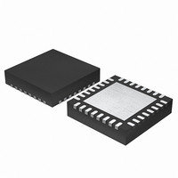
EFM32G200F16 Energy Micro, EFM32G200F16 Datasheet - Page 294

EFM32G200F16
Manufacturer Part Number
EFM32G200F16
Description
MCU 32BIT 16KB FLASH 32-QFN
Manufacturer
Energy Micro
Series
Geckor
Datasheets
1.EFM32G200F16.pdf
(63 pages)
2.EFM32G200F16.pdf
(10 pages)
3.EFM32G200F16.pdf
(463 pages)
4.EFM32G200F16.pdf
(136 pages)
Specifications of EFM32G200F16
Core Processor
ARM® Cortex-M3™
Core Size
32-Bit
Speed
32MHz
Connectivity
EBI/EMI, I²C, IrDA, SmartCard, SPI, UART/USART
Peripherals
Brown-out Detect/Reset, DMA, POR, PWM, WDT
Number Of I /o
24
Program Memory Size
16KB (16K x 8)
Program Memory Type
FLASH
Ram Size
8K x 8
Voltage - Supply (vcc/vdd)
1.8 V ~ 3.8 V
Data Converters
A/D 4x12b, D/A 1x12b
Oscillator Type
External
Operating Temperature
-40°C ~ 85°C
Package / Case
32-VQFN Exposed Pad
Processor Series
EFM32G200
Core
ARM Cortex-M3
Data Bus Width
32 bit
Data Ram Size
8 KB
Interface Type
I2C, UART
Maximum Clock Frequency
32 MHz
Number Of Programmable I/os
24
Number Of Timers
2
Operating Supply Voltage
1.8 V to 3.8 V
Maximum Operating Temperature
+ 85 C
Mounting Style
SMD/SMT
Minimum Operating Temperature
- 40 C
Lead Free Status / RoHS Status
Lead free / RoHS Compliant
Eeprom Size
-
Lead Free Status / Rohs Status
Details
- EFM32G200F16 PDF datasheet
- EFM32G200F16 PDF datasheet #2
- EFM32G200F16 PDF datasheet #3
- EFM32G200F16 PDF datasheet #4
- Current page: 294 of 463
- Download datasheet (8Mb)
21.3.5 Examples
21.3.5.1 Triggered Output Generation
2010-09-06 - d0001_Rev1.00
This section presents a couple of usage examples for the LETIMER.
Example 21.1. LETIMER Triggered Output Generation
If both LETIMERn_CNT and LETIMERn_REP0 are 0 in buffered mode, and COMP0TOP and BUFTOP
in LETIMERn_CTRL are set, the values of LETIMERn_COMP1 and LETIMERn_REP1 are loaded into
LETIMERn_CNT and LETIMERn_REP0 respectively when the timer is started. If no additional writes to
LETIMERn_REP1 are done before the timer stops, LETIMERn_REP1 determines the number of pulses/
toggles generated on the output, and LETIMERn_COMP1 determines the period lengths.
As the RTC can be used to start the LETIMER, the RTC and LETIMER can thus be combined to generate
specific pulse-trains at given intervals. Software can update LETIMERn_COMP1 and LETIMERn_REP1
to change the number of pulses and pulse-period in each train, but if changes are not required, software
does not have to update the registers between each pulse train.
For the example in Figure 21.9 (p. 294) , the initial values cause the LETIMER to generate two pulses
with 3 cycle periods, or a single pulse 3 cycles wide every time the LETIMER is started. After the output
has been generated, the LETIMER stops, and is ready to be triggered again.
Figure 21.9. LETIMER Triggered Operation
LFACLK
UFOA0 = 01
UFOA0 = 10
Int. flags set
LETn_O0
LETn_O1
LETIMERn
TOP1
TOP0
REP0
REP1
Initial configuration,
CNT
REP1 just written
X
2
0
0
2
2
2
2
2
2
u
2
2
2
1
2
u
UFIF
2
2
2
0
2
u
2
2
2
2
1
u
2
2
2
1
1
REP0IF
u
UFIF
2
2
2
0
1
Stop
u
2
2
2
0
0
u
2
2
2
0
0
u
2
2
2
0
0
START= 1
u
...the world's most energy friendly microcontrollers
Write
2
2
2
0
0
294
u
2
2
2
0
0
u
2
2
2
2
2
u
UFIF
2
2
2
1
2
u
2
2
2
0
2
u
2
2
2
2
1
u
2
2
2
1
1
REP0IF
u
UFIF
2
2
2
0
1
Stop
u
2
2
2
0
0
START= 1
u
Write
2
2
2
0
0
u
www.energymicro.com
2
2
2
0
0
u
2
2
2
2
2
u
UFIF
2
2
2
1
2
u
2
2
2
0
2
u
Related parts for EFM32G200F16
Image
Part Number
Description
Manufacturer
Datasheet
Request
R

Part Number:
Description:
KIT STARTER EFM32 GECKO
Manufacturer:
Energy Micro
Datasheet:

Part Number:
Description:
KIT DEV EFM32 GECKO LCD SUPPORT
Manufacturer:
Energy Micro
Datasheet:

Part Number:
Description:
BOARD PROTOTYPING FOR EFM32
Manufacturer:
Energy Micro
Datasheet:

Part Number:
Description:
KIT DEVELOPMENT EFM32 GECKO
Manufacturer:
Energy Micro
Datasheet:

Part Number:
Description:
MCU, MPU & DSP Development Tools TG840 Sample Kit
Manufacturer:
Energy Micro
Datasheet:

Part Number:
Description:
MCU, MPU & DSP Development Tools TG Starter Kit
Manufacturer:
Energy Micro
Datasheet:

Part Number:
Description:
MCU, MPU & DSP Development Tools TG108 Sample Kit
Manufacturer:
Energy Micro

Part Number:
Description:
MCU, MPU & DSP Development Tools TG210 Sample Kit
Manufacturer:
Energy Micro
Datasheet:

Part Number:
Description:
MCU, MPU & DSP Development Tools TG822 Sample Kit
Manufacturer:
Energy Micro
Datasheet:

Part Number:
Description:
MCU, MPU & DSP Development Tools TG230 Sample Kit
Manufacturer:
Energy Micro

Part Number:
Description:
SAMPLE KIT (SMALL BOX - CONTAINING 2 DEVICES)
Manufacturer:
Energy Micro

Part Number:
Description:
SAMPLE KIT (SMALL BOX - CONTAINING 2 DEVICES)
Manufacturer:
Energy Micro


