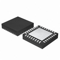
EFM32G200F16 Energy Micro, EFM32G200F16 Datasheet - Page 249

EFM32G200F16
Manufacturer Part Number
EFM32G200F16
Description
MCU 32BIT 16KB FLASH 32-QFN
Manufacturer
Energy Micro
Series
Geckor
Datasheets
1.EFM32G200F16.pdf
(63 pages)
2.EFM32G200F16.pdf
(10 pages)
3.EFM32G200F16.pdf
(463 pages)
4.EFM32G200F16.pdf
(136 pages)
Specifications of EFM32G200F16
Core Processor
ARM® Cortex-M3™
Core Size
32-Bit
Speed
32MHz
Connectivity
EBI/EMI, I²C, IrDA, SmartCard, SPI, UART/USART
Peripherals
Brown-out Detect/Reset, DMA, POR, PWM, WDT
Number Of I /o
24
Program Memory Size
16KB (16K x 8)
Program Memory Type
FLASH
Ram Size
8K x 8
Voltage - Supply (vcc/vdd)
1.8 V ~ 3.8 V
Data Converters
A/D 4x12b, D/A 1x12b
Oscillator Type
External
Operating Temperature
-40°C ~ 85°C
Package / Case
32-VQFN Exposed Pad
Processor Series
EFM32G200
Core
ARM Cortex-M3
Data Bus Width
32 bit
Data Ram Size
8 KB
Interface Type
I2C, UART
Maximum Clock Frequency
32 MHz
Number Of Programmable I/os
24
Number Of Timers
2
Operating Supply Voltage
1.8 V to 3.8 V
Maximum Operating Temperature
+ 85 C
Mounting Style
SMD/SMT
Minimum Operating Temperature
- 40 C
Lead Free Status / RoHS Status
Lead free / RoHS Compliant
Eeprom Size
-
Lead Free Status / Rohs Status
Details
- EFM32G200F16 PDF datasheet
- EFM32G200F16 PDF datasheet #2
- EFM32G200F16 PDF datasheet #3
- EFM32G200F16 PDF datasheet #4
- Current page: 249 of 463
- Download datasheet (8Mb)
19.3.2.1 Input Pin Logic
19.3.2.2 Compare/Capture Registers
19.3.2.2.1 Input Capture mode
19.3.2.2.2 Compare and PWM Mode
2010-09-06 - d0001_Rev1.00
2. Output Compare
3. PWM
Each Compare/Capture channel can be configured as an input source for the Capture Unit or as external
clock source for the Timer (see Figure 19.10 (p. 249) ). Compare/Capture channels 0 and 1 are the
inputs for the Quadrature Decoder Mode. The input channel can be filtered before it is used, which
requires the input to remain stable for 5 cycles in a row before the input is propagated to the output.
Figure 19.10. TIMER Input Pin Logic
The Compare/Capture channel registers are prefixed with TIMERn_CCx_, where the x stands for the
channel number. Since the Compare/Capture channels serve three functions (input capture, compare,
PWM), the behavior of the Compare/Capture registers (TIMERn_CCx_CCV) and buffer registers
(TIMERn_CCx_CCVB) change depending on the mode the channel is set in.
When running in Input Capture mode, TIMERn_CCx_CCV and TIMERn_CCx_CCVB form a FIFO buffer,
and new capture values are added on a capture event, see Figure 19.11 (p. 249) . The first capture
can always be read from TIMERn_CCx_CCV, and reading this address will load the next capture value
into TIMERn_CCx_CCV from TIMERn_CCx_CCVB if it contains valid data. The CC value can be read
without altering the FIFO contents by reading TIMERn_CCx_CCVP. TIMERn_CCx_CCVB can also be
read without altering the FIFO contents. The ICV flag in TIMERn_STATUS indicates if there is a valid
unread capture in TIMERn_CCx_CCV.
In case a capture is triggered while both CCV and CCVB contain unread capture values, the buffer
overflow interrupt flag (ICBOF in TIMERn_IF) will be set. New capture values will on overflow overwrite
the value in TIMERn_CCx_CCVB.
Figure 19.11. TIMER Input Capture Buffer Functionality
When running in Output Compare or PWM mode, the value in TIMERn_CCx_CCV will be compared
against the count value. In Compare mode the output can be configured to toggle, clear or set
FIFO
PRS channels
TIMn_CCx
CCV B
CN T
CCV
PRSSEL
INSEL
Filter
FILT
...the world's most energy friendly microcontrollers
ICEDGE
249
Capture x
Input
www.energymicro.com
Related parts for EFM32G200F16
Image
Part Number
Description
Manufacturer
Datasheet
Request
R

Part Number:
Description:
KIT STARTER EFM32 GECKO
Manufacturer:
Energy Micro
Datasheet:

Part Number:
Description:
KIT DEV EFM32 GECKO LCD SUPPORT
Manufacturer:
Energy Micro
Datasheet:

Part Number:
Description:
BOARD PROTOTYPING FOR EFM32
Manufacturer:
Energy Micro
Datasheet:

Part Number:
Description:
KIT DEVELOPMENT EFM32 GECKO
Manufacturer:
Energy Micro
Datasheet:

Part Number:
Description:
MCU, MPU & DSP Development Tools TG840 Sample Kit
Manufacturer:
Energy Micro
Datasheet:

Part Number:
Description:
MCU, MPU & DSP Development Tools TG Starter Kit
Manufacturer:
Energy Micro
Datasheet:

Part Number:
Description:
MCU, MPU & DSP Development Tools TG108 Sample Kit
Manufacturer:
Energy Micro

Part Number:
Description:
MCU, MPU & DSP Development Tools TG210 Sample Kit
Manufacturer:
Energy Micro
Datasheet:

Part Number:
Description:
MCU, MPU & DSP Development Tools TG822 Sample Kit
Manufacturer:
Energy Micro
Datasheet:

Part Number:
Description:
MCU, MPU & DSP Development Tools TG230 Sample Kit
Manufacturer:
Energy Micro

Part Number:
Description:
SAMPLE KIT (SMALL BOX - CONTAINING 2 DEVICES)
Manufacturer:
Energy Micro

Part Number:
Description:
SAMPLE KIT (SMALL BOX - CONTAINING 2 DEVICES)
Manufacturer:
Energy Micro


