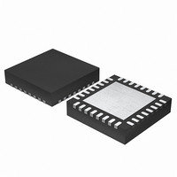
EFM32G200F16 Energy Micro, EFM32G200F16 Datasheet - Page 350

EFM32G200F16
Manufacturer Part Number
EFM32G200F16
Description
MCU 32BIT 16KB FLASH 32-QFN
Manufacturer
Energy Micro
Series
Geckor
Datasheets
1.EFM32G200F16.pdf
(63 pages)
2.EFM32G200F16.pdf
(10 pages)
3.EFM32G200F16.pdf
(463 pages)
4.EFM32G200F16.pdf
(136 pages)
Specifications of EFM32G200F16
Core Processor
ARM® Cortex-M3™
Core Size
32-Bit
Speed
32MHz
Connectivity
EBI/EMI, I²C, IrDA, SmartCard, SPI, UART/USART
Peripherals
Brown-out Detect/Reset, DMA, POR, PWM, WDT
Number Of I /o
24
Program Memory Size
16KB (16K x 8)
Program Memory Type
FLASH
Ram Size
8K x 8
Voltage - Supply (vcc/vdd)
1.8 V ~ 3.8 V
Data Converters
A/D 4x12b, D/A 1x12b
Oscillator Type
External
Operating Temperature
-40°C ~ 85°C
Package / Case
32-VQFN Exposed Pad
Processor Series
EFM32G200
Core
ARM Cortex-M3
Data Bus Width
32 bit
Data Ram Size
8 KB
Interface Type
I2C, UART
Maximum Clock Frequency
32 MHz
Number Of Programmable I/os
24
Number Of Timers
2
Operating Supply Voltage
1.8 V to 3.8 V
Maximum Operating Temperature
+ 85 C
Mounting Style
SMD/SMT
Minimum Operating Temperature
- 40 C
Lead Free Status / RoHS Status
Lead free / RoHS Compliant
Eeprom Size
-
Lead Free Status / Rohs Status
Details
- EFM32G200F16 PDF datasheet
- EFM32G200F16 PDF datasheet #2
- EFM32G200F16 PDF datasheet #3
- EFM32G200F16 PDF datasheet #4
- Current page: 350 of 463
- Download datasheet (8Mb)
25.5.2 ADCn_CMD - Command Register
23:21
20:16
15
14:8
7:6
5:4
3
2
1:0
Bit
Offset
0x004
Reset
Access
Name
2010-09-06 - d0001_Rev1.00
Reserved
TIMEBASE
Set time base used for ADC warm up sequence according to the HFPERCLK frequency. The time base is defined as a number of
HFPERCLK cycles which should be set equal to or higher than 1us.
Reserved
PRESC
Select clock division factor.
Reserved
LPFMODE
These bits control the filtering of the ADC input. Details on the filter characteristics can be found in the device datasheets.
TAILGATE
Enable/disable conversion tailgating.
Reserved
WARMUPMODE
Select Warm-up Mode for ADC
Name
Value
9
10
11
Value
TIMEBASE
Value
PRESC
Value
0
1
2
Value
0
1
Value
0
1
2
3
Mode
X1024
X2048
X4096
Mode
BYPASS
DECAP
RCFILT
Mode
NORMAL
FASTBG
KEEPSCANREFWARM
KEEPADCWARM
Description
Scan sequence has priority, but can be delayed by ongoing single samples.
Scan sequence has priority and single samples will only start immediately after scan sequence.
0x1F
0x00
0x0
0
0x0
Reset
To ensure compatibility with future devices, always write bits to 0. More information in Section 2.1 (p. 3)
To ensure compatibility with future devices, always write bits to 0. More information in Section 2.1 (p. 3)
To ensure compatibility with future devices, always write bits to 0. More information in Section 2.1 (p. 3)
To ensure compatibility with future devices, always write bits to 0. More information in Section 2.1 (p. 3)
RW
RW
RW
RW
RW
Access
Description
Clock division factor of PRESC+1.
Description
1024 samples for each conversion result
2048 samples for each conversion result
4096 samples for each conversion result
Description
No filter or decoupling capacitor
On chip decoupling capacitor selected
On chip RC filter selected
Description
ADC is shut down after each conversion
Bandgap references do not need warm up, but have reduced accuracy.
Reference selected for scan mode is kept warm.
ADC is kept warmed up and scan reference is kept warm
...the world's most energy friendly microcontrollers
350
Bit Position
Description
ADC warm-up is set to TIMEBASE+1 HFPERCLK clock cycles and bandgap
warm-up is set to 5x(TIMEBASE+1) HFPERCLK cycles.
Time Base
Prescaler Setting
Low Pass Filter Mode
Conversion Tailgating
Warm-up Mode
Description
www.energymicro.com
Related parts for EFM32G200F16
Image
Part Number
Description
Manufacturer
Datasheet
Request
R

Part Number:
Description:
KIT STARTER EFM32 GECKO
Manufacturer:
Energy Micro
Datasheet:

Part Number:
Description:
KIT DEV EFM32 GECKO LCD SUPPORT
Manufacturer:
Energy Micro
Datasheet:

Part Number:
Description:
BOARD PROTOTYPING FOR EFM32
Manufacturer:
Energy Micro
Datasheet:

Part Number:
Description:
KIT DEVELOPMENT EFM32 GECKO
Manufacturer:
Energy Micro
Datasheet:

Part Number:
Description:
MCU, MPU & DSP Development Tools TG840 Sample Kit
Manufacturer:
Energy Micro
Datasheet:

Part Number:
Description:
MCU, MPU & DSP Development Tools TG Starter Kit
Manufacturer:
Energy Micro
Datasheet:

Part Number:
Description:
MCU, MPU & DSP Development Tools TG108 Sample Kit
Manufacturer:
Energy Micro

Part Number:
Description:
MCU, MPU & DSP Development Tools TG210 Sample Kit
Manufacturer:
Energy Micro
Datasheet:

Part Number:
Description:
MCU, MPU & DSP Development Tools TG822 Sample Kit
Manufacturer:
Energy Micro
Datasheet:

Part Number:
Description:
MCU, MPU & DSP Development Tools TG230 Sample Kit
Manufacturer:
Energy Micro

Part Number:
Description:
SAMPLE KIT (SMALL BOX - CONTAINING 2 DEVICES)
Manufacturer:
Energy Micro

Part Number:
Description:
SAMPLE KIT (SMALL BOX - CONTAINING 2 DEVICES)
Manufacturer:
Energy Micro


