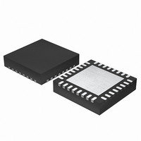
EFM32G200F16 Energy Micro, EFM32G200F16 Datasheet - Page 192

EFM32G200F16
Manufacturer Part Number
EFM32G200F16
Description
MCU 32BIT 16KB FLASH 32-QFN
Manufacturer
Energy Micro
Series
Geckor
Datasheets
1.EFM32G200F16.pdf
(63 pages)
2.EFM32G200F16.pdf
(10 pages)
3.EFM32G200F16.pdf
(463 pages)
4.EFM32G200F16.pdf
(136 pages)
Specifications of EFM32G200F16
Core Processor
ARM® Cortex-M3™
Core Size
32-Bit
Speed
32MHz
Connectivity
EBI/EMI, I²C, IrDA, SmartCard, SPI, UART/USART
Peripherals
Brown-out Detect/Reset, DMA, POR, PWM, WDT
Number Of I /o
24
Program Memory Size
16KB (16K x 8)
Program Memory Type
FLASH
Ram Size
8K x 8
Voltage - Supply (vcc/vdd)
1.8 V ~ 3.8 V
Data Converters
A/D 4x12b, D/A 1x12b
Oscillator Type
External
Operating Temperature
-40°C ~ 85°C
Package / Case
32-VQFN Exposed Pad
Processor Series
EFM32G200
Core
ARM Cortex-M3
Data Bus Width
32 bit
Data Ram Size
8 KB
Interface Type
I2C, UART
Maximum Clock Frequency
32 MHz
Number Of Programmable I/os
24
Number Of Timers
2
Operating Supply Voltage
1.8 V to 3.8 V
Maximum Operating Temperature
+ 85 C
Mounting Style
SMD/SMT
Minimum Operating Temperature
- 40 C
Lead Free Status / RoHS Status
Lead free / RoHS Compliant
Eeprom Size
-
Lead Free Status / Rohs Status
Details
- EFM32G200F16 PDF datasheet
- EFM32G200F16 PDF datasheet #2
- EFM32G200F16 PDF datasheet #3
- EFM32G200F16 PDF datasheet #4
- Current page: 192 of 463
- Download datasheet (8Mb)
16.3.3.3 Master Mode
2010-09-06 - d0001_Rev1.00
USART Synchronous Mode Clock Division Factor
When the USART operates in master mode, the highest possible bit rate is half the peripheral clock rate.
When operating in slave mode however, the highest bit rate is an eight of the peripheral clock:
• Master mode: br
• Slave mode: br
On every clock edge data on the data lines, MOSI and MISO, is either set up or sampled. When CLKPHA
in USARTn_CTRL is cleared, data is sampled on the leading clock edge and set-up is done on the
trailing edge. If CLKPHA is set however, data is set-up on the leading clock edge, and sampled on the
trailing edge. In addition to this, the polarity of the clock signal can be changed by setting CLKPOL in
USARTn_CTRL, which also defines the idle state of the clock. This results in four different modes which
are summarized in Table 16.8 (p. 192) . Figure 16.15 (p. 192) shows the resulting timing of data
set-up and sampling relative to the bus clock.
Table 16.8. USART SPI Modes
Figure 16.15. USART SPI Timing
If CPHA=1, the TX underflow flag, TXUF, will be set on the first setup clock edge of a frame in slave
mode if TX data is not available. If CPHA=0, TXUF is set if data is not available in the transmit buffer
three HFPERCLK cycles prior to the first sample clock edge. The RXDATAV flag is updated on the last
sample clock edge of a transfer, while the RX overflow interrupt flag, RXOF, is set on the first sample
clock edge if the receive buffer overflows. When a transfer has been performed, interrupt flags TXBL
and TXC are updated on the first setup clock edge of the succeeding frame, or when CS is deasserted.
When in master mode, the USART is in full control of the data flow on the synchronous bus. When
operating in full duplex mode, the slave cannot transmit data to the master without the master transmitting
to the slave. The master outputs the bus clock on USn_CLK.
SPI mode
0
1
2
3
USn_CLK
USn_TX/
USn_CS
USn_RX
CLKPOL = 0
CLKPOL = 1
CLKPHA = 1
CLKPHA = 0
CLKPOL
0
0
1
1
max
USARTn_CLKDIV = 256 x (f
max
= f
X
= f
HFPERCLK
X
HFPERCLK
0
CLKPHA
0
1
0
1
0
/8
1
/2
1
2
2
Leading edge
Rising, sample
Rising, set-up
Falling, sample
Falling, set-up
3
HFPERCLK
...the world's most energy friendly microcontrollers
3
192
4
4
/(2 x brdesired) - 1)
5
5
6
6
7
7
Trailing edge
Falling, set-up
Falling, sample
Rising, set-up
Rising, sample
X
X
www.energymicro.com
(16.4)
Related parts for EFM32G200F16
Image
Part Number
Description
Manufacturer
Datasheet
Request
R

Part Number:
Description:
KIT STARTER EFM32 GECKO
Manufacturer:
Energy Micro
Datasheet:

Part Number:
Description:
KIT DEV EFM32 GECKO LCD SUPPORT
Manufacturer:
Energy Micro
Datasheet:

Part Number:
Description:
BOARD PROTOTYPING FOR EFM32
Manufacturer:
Energy Micro
Datasheet:

Part Number:
Description:
KIT DEVELOPMENT EFM32 GECKO
Manufacturer:
Energy Micro
Datasheet:

Part Number:
Description:
MCU, MPU & DSP Development Tools TG840 Sample Kit
Manufacturer:
Energy Micro
Datasheet:

Part Number:
Description:
MCU, MPU & DSP Development Tools TG Starter Kit
Manufacturer:
Energy Micro
Datasheet:

Part Number:
Description:
MCU, MPU & DSP Development Tools TG108 Sample Kit
Manufacturer:
Energy Micro

Part Number:
Description:
MCU, MPU & DSP Development Tools TG210 Sample Kit
Manufacturer:
Energy Micro
Datasheet:

Part Number:
Description:
MCU, MPU & DSP Development Tools TG822 Sample Kit
Manufacturer:
Energy Micro
Datasheet:

Part Number:
Description:
MCU, MPU & DSP Development Tools TG230 Sample Kit
Manufacturer:
Energy Micro

Part Number:
Description:
SAMPLE KIT (SMALL BOX - CONTAINING 2 DEVICES)
Manufacturer:
Energy Micro

Part Number:
Description:
SAMPLE KIT (SMALL BOX - CONTAINING 2 DEVICES)
Manufacturer:
Energy Micro


