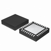
EFM32G200F16 Energy Micro, EFM32G200F16 Datasheet - Page 255

EFM32G200F16
Manufacturer Part Number
EFM32G200F16
Description
MCU 32BIT 16KB FLASH 32-QFN
Manufacturer
Energy Micro
Series
Geckor
Datasheets
1.EFM32G200F16.pdf
(63 pages)
2.EFM32G200F16.pdf
(10 pages)
3.EFM32G200F16.pdf
(463 pages)
4.EFM32G200F16.pdf
(136 pages)
Specifications of EFM32G200F16
Core Processor
ARM® Cortex-M3™
Core Size
32-Bit
Speed
32MHz
Connectivity
EBI/EMI, I²C, IrDA, SmartCard, SPI, UART/USART
Peripherals
Brown-out Detect/Reset, DMA, POR, PWM, WDT
Number Of I /o
24
Program Memory Size
16KB (16K x 8)
Program Memory Type
FLASH
Ram Size
8K x 8
Voltage - Supply (vcc/vdd)
1.8 V ~ 3.8 V
Data Converters
A/D 4x12b, D/A 1x12b
Oscillator Type
External
Operating Temperature
-40°C ~ 85°C
Package / Case
32-VQFN Exposed Pad
Processor Series
EFM32G200
Core
ARM Cortex-M3
Data Bus Width
32 bit
Data Ram Size
8 KB
Interface Type
I2C, UART
Maximum Clock Frequency
32 MHz
Number Of Programmable I/os
24
Number Of Timers
2
Operating Supply Voltage
1.8 V to 3.8 V
Maximum Operating Temperature
+ 85 C
Mounting Style
SMD/SMT
Minimum Operating Temperature
- 40 C
Lead Free Status / RoHS Status
Lead free / RoHS Compliant
Eeprom Size
-
Lead Free Status / Rohs Status
Details
- EFM32G200F16 PDF datasheet
- EFM32G200F16 PDF datasheet #2
- EFM32G200F16 PDF datasheet #3
- EFM32G200F16 PDF datasheet #4
- Current page: 255 of 463
- Download datasheet (8Mb)
19.3.3.1 Output Polarity
2010-09-06 - d0001_Rev1.00
Dead-time is specified individually for the rising and falling edge of the original PWM. These values
are shared across all the three PWM channels of the DTI unit. A single prescaler value is provided
for the DTI unit, meaning that both the rising and falling edge dead-times share prescaler value. The
prescaler divides the HFPERCLK
DTPRESC field in TIMER0_DTTIME. The rising and falling edge dead-times are configured in DTRISET
and DTFALLT in TIMER0_DTTIME to any number between 1-64 HFPERCLK
The value of the primary and complementary outputs in a pair will never be set active at the same time by
the DTI unit. The polarity of the outputs can be changed however, if this is required by the application. The
active values of the primary and complementary outputs are set by two the TIMER0_DTCTRL register.
The DTIPOL bit of this register specifies the base polarity. If DTIPOL =0, then the outputs are active-high,
and if DTIPOL = 1 they are active-low. The relative phase of the primary and complementary outputs is
not changed by DTIPOL, as the polarity of both outputs is changed, see Figure 19.24 (p. 255)
In some applications, it may be required that the primary outputs are active-high, while the
complementary outputs are active-low. This can be accomplished by manipulating the DTCINV bit of
the TIMER0_DTCTRL register, which inverts the polarity of the complementary outputs relative to the
primary outputs.
Example 19.1. TIMER DTI Example 1
DTIPOL = 0 and DTCINV = 0 results in outputs with opposite phase and active-high states.
Example 19.2. TIMER DTI Example 2
DTIPOL = 1 and DTCINV = 1 results in outputs with equal phase. The primary output will be active-high,
while the complementary will be active-low
Figure 19.24. TIMER Output Polarities
Output generation on the individual DTI outputs can be disabled by configuring TIMER0_DTOGEN.
When output generation on an output is disabled, it will go to and stay in its inactive state.
DTIPOL = 0
DTCINV = 0
DTIPOL = 1
DTCINV = 0
DTIPOL = 0
DTCINV = 1
DTIPOL = 1
DTCINV = 1
Original PWM
TIM0_CDTI0
TIM0_CDTI0
TIM0_CDTI0
TIM0_CDTI0
TIM0_CC0
TIM0_CC0
TIM0_CC0
TIM0_CC0
TIMERn
by a configurable factor between 1 and 1024, which is set in the
...the world's most energy friendly microcontrollers
255
TIMER0
www.energymicro.com
cycles.
Related parts for EFM32G200F16
Image
Part Number
Description
Manufacturer
Datasheet
Request
R

Part Number:
Description:
KIT STARTER EFM32 GECKO
Manufacturer:
Energy Micro
Datasheet:

Part Number:
Description:
KIT DEV EFM32 GECKO LCD SUPPORT
Manufacturer:
Energy Micro
Datasheet:

Part Number:
Description:
BOARD PROTOTYPING FOR EFM32
Manufacturer:
Energy Micro
Datasheet:

Part Number:
Description:
KIT DEVELOPMENT EFM32 GECKO
Manufacturer:
Energy Micro
Datasheet:

Part Number:
Description:
MCU, MPU & DSP Development Tools TG840 Sample Kit
Manufacturer:
Energy Micro
Datasheet:

Part Number:
Description:
MCU, MPU & DSP Development Tools TG Starter Kit
Manufacturer:
Energy Micro
Datasheet:

Part Number:
Description:
MCU, MPU & DSP Development Tools TG108 Sample Kit
Manufacturer:
Energy Micro

Part Number:
Description:
MCU, MPU & DSP Development Tools TG210 Sample Kit
Manufacturer:
Energy Micro
Datasheet:

Part Number:
Description:
MCU, MPU & DSP Development Tools TG822 Sample Kit
Manufacturer:
Energy Micro
Datasheet:

Part Number:
Description:
MCU, MPU & DSP Development Tools TG230 Sample Kit
Manufacturer:
Energy Micro

Part Number:
Description:
SAMPLE KIT (SMALL BOX - CONTAINING 2 DEVICES)
Manufacturer:
Energy Micro

Part Number:
Description:
SAMPLE KIT (SMALL BOX - CONTAINING 2 DEVICES)
Manufacturer:
Energy Micro


