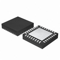
EFM32G200F16 Energy Micro, EFM32G200F16 Datasheet - Page 456

EFM32G200F16
Manufacturer Part Number
EFM32G200F16
Description
MCU 32BIT 16KB FLASH 32-QFN
Manufacturer
Energy Micro
Series
Geckor
Datasheets
1.EFM32G200F16.pdf
(63 pages)
2.EFM32G200F16.pdf
(10 pages)
3.EFM32G200F16.pdf
(463 pages)
4.EFM32G200F16.pdf
(136 pages)
Specifications of EFM32G200F16
Core Processor
ARM® Cortex-M3™
Core Size
32-Bit
Speed
32MHz
Connectivity
EBI/EMI, I²C, IrDA, SmartCard, SPI, UART/USART
Peripherals
Brown-out Detect/Reset, DMA, POR, PWM, WDT
Number Of I /o
24
Program Memory Size
16KB (16K x 8)
Program Memory Type
FLASH
Ram Size
8K x 8
Voltage - Supply (vcc/vdd)
1.8 V ~ 3.8 V
Data Converters
A/D 4x12b, D/A 1x12b
Oscillator Type
External
Operating Temperature
-40°C ~ 85°C
Package / Case
32-VQFN Exposed Pad
Processor Series
EFM32G200
Core
ARM Cortex-M3
Data Bus Width
32 bit
Data Ram Size
8 KB
Interface Type
I2C, UART
Maximum Clock Frequency
32 MHz
Number Of Programmable I/os
24
Number Of Timers
2
Operating Supply Voltage
1.8 V to 3.8 V
Maximum Operating Temperature
+ 85 C
Mounting Style
SMD/SMT
Minimum Operating Temperature
- 40 C
Lead Free Status / RoHS Status
Lead free / RoHS Compliant
Eeprom Size
-
Lead Free Status / Rohs Status
Details
- EFM32G200F16 PDF datasheet
- EFM32G200F16 PDF datasheet #2
- EFM32G200F16 PDF datasheet #3
- EFM32G200F16 PDF datasheet #4
- Current page: 456 of 463
- Download datasheet (8Mb)
2010-09-06 - d0001_Rev1.00
List of Figures
3.1. Diagram of EFM32G .............................................................................................................................. 7
3.2. Energy Mode indicator ............................................................................................................................. 7
4.1. Interrupt Operation ................................................................................................................................ 11
5.1. System Address Space .......................................................................................................................... 14
5.2. Write operation to Low Energy Peripherals ................................................................................................ 19
5.3. Read operation form Low Energy Peripherals ............................................................................................. 20
6.1. AAP - Authentication Access Port ............................................................................................................ 24
7.1. Revision Number Extraction .................................................................................................................... 29
8.1. DMA Block Diagram .............................................................................................................................. 39
8.2. Polling flowchart .................................................................................................................................... 42
8.3. Ping-pong example ................................................................................................................................ 44
8.4. Memory scatter-gather example ............................................................................................................... 47
8.5. Peripheral scatter-gather example ............................................................................................................ 49
8.6. Memory map for 8 channels, including the alternate data structure ................................................................. 51
8.7. Detailed memory map for the 8 channels, including the alternate data structure ................................................. 52
8.8. channel_cfg bit assignments ................................................................................................................... 53
9.1. RMU Reset Input Sources and Connections. .............................................................................................. 76
9.2. RMU Power-on Reset Operation .............................................................................................................. 77
9.3. RMU Brown-out Detector Operation .......................................................................................................... 77
10.1. EMU Overview .................................................................................................................................... 82
10.2. EMU Energy Mode Transitions .............................................................................................................. 83
11.1. CMU Overview .................................................................................................................................... 92
11.2. CMU Switching from HFRCO to HFXO before HFXO is ready ...................................................................... 95
11.3. CMU Switching from HFRCO to HFXO after HFXO is ready ........................................................................ 96
11.4. HFXO Pin Connection .......................................................................................................................... 96
11.5. LFXO Pin Connection .......................................................................................................................... 97
11.6. HW-support for RC Oscillator Calibration ................................................................................................. 97
13.1. PRS Overview ................................................................................................................................... 125
13.2. TIMER0 overflow starting ADC0 single conversions through PRS channel 5. ................................................. 127
14.1. EBI Overview .................................................................................................................................... 133
14.2. EBI 8-bit Read Operation .................................................................................................................... 133
14.3. EBI 8-bit Write Operation .................................................................................................................... 133
14.4. EBI Address Latch Setup .................................................................................................................... 134
14.5. EBI 16-bit Read Operation .................................................................................................................. 134
14.6. EBI 16-bit Write Operation ................................................................................................................... 134
14.7. EBI 24-bit Read Operation .................................................................................................................. 135
14.8. EBI 24-bit Write Operation ................................................................................................................... 135
15.1. I
15.2. I
15.3. I
15.4. I
15.5. I
15.6. I
15.7. I
15.8. I
15.9. I
15.10. I
15.11. I
16.1. USART Overview ............................................................................................................................... 176
16.2. USART Asynchronous Frame Format .................................................................................................... 177
16.3. USART Transmit Buffer Operation ........................................................................................................ 181
16.4. USART Receive Buffer Operation ......................................................................................................... 183
16.5. USART Sampling of Start and Data Bits ................................................................................................ 184
16.6. USART Sampling of Stop Bits when Number of Stop Bits are 1 or More ....................................................... 184
16.7. USART Local Loopback ...................................................................................................................... 185
16.8. USART Half Duplex Communication with External Driver ........................................................................... 186
16.9. USART Transmission of Large Frames .................................................................................................. 187
16.10. USART Transmission of Large Frames, MSBF ...................................................................................... 188
16.11. USART Reception of Large Frames ..................................................................................................... 188
16.12. USART ISO 7816 Data Frame Without Error ......................................................................................... 190
16.13. USART ISO 7816 Data Frame With Error ............................................................................................. 190
16.14. USART SmartCard Stop Bit Sampling .................................................................................................. 191
16.15. USART SPI Timing .......................................................................................................................... 192
16.16. USART Example RZI Signal for a given Asynchronous USART Frame ....................................................... 195
18.1. LEUART Overview ............................................................................................................................. 218
18.2. LEUART Asynchronous Frame Format .................................................................................................. 219
18.3. LEUART Transmitter Overview ............................................................................................................. 221
18.4. LEUART Receiver Overview ................................................................................................................ 223
18.5. LEUART Local Loopback .................................................................................................................... 226
18.6. LEUART Half Duplex Communication with External Driver ......................................................................... 226
18.7. LEUART - NRZ vs. RZI ...................................................................................................................... 228
2
2
2
2
2
2
2
2
2
C Single Byte Write, then Repeated Start and Single Byte Read ............................................................... 145
C Master Transmitter/Slave Receiver with 10-bit Address ........................................................................ 146
C Master Receiver/Slave Transmitter with 10-bit Address ........................................................................ 146
C Overview .................................................................................................................................... 143
C-Bus Example ............................................................................................................................... 143
C START and STOP Conditions ......................................................................................................... 144
C Bit Transfer on I
C Single Byte Write to Slave ............................................................................................................. 145
C Double Byte Read from Slave ......................................................................................................... 145
2
2
C Master State Machine .................................................................................................................. 149
C Slave State Machine ................................................................................................................... 156
2
C-Bus ................................................................................................................. 144
...the world's most energy friendly microcontrollers
456
www.energymicro.com
Related parts for EFM32G200F16
Image
Part Number
Description
Manufacturer
Datasheet
Request
R

Part Number:
Description:
KIT STARTER EFM32 GECKO
Manufacturer:
Energy Micro
Datasheet:

Part Number:
Description:
KIT DEV EFM32 GECKO LCD SUPPORT
Manufacturer:
Energy Micro
Datasheet:

Part Number:
Description:
BOARD PROTOTYPING FOR EFM32
Manufacturer:
Energy Micro
Datasheet:

Part Number:
Description:
KIT DEVELOPMENT EFM32 GECKO
Manufacturer:
Energy Micro
Datasheet:

Part Number:
Description:
MCU, MPU & DSP Development Tools TG840 Sample Kit
Manufacturer:
Energy Micro
Datasheet:

Part Number:
Description:
MCU, MPU & DSP Development Tools TG Starter Kit
Manufacturer:
Energy Micro
Datasheet:

Part Number:
Description:
MCU, MPU & DSP Development Tools TG108 Sample Kit
Manufacturer:
Energy Micro

Part Number:
Description:
MCU, MPU & DSP Development Tools TG210 Sample Kit
Manufacturer:
Energy Micro
Datasheet:

Part Number:
Description:
MCU, MPU & DSP Development Tools TG822 Sample Kit
Manufacturer:
Energy Micro
Datasheet:

Part Number:
Description:
MCU, MPU & DSP Development Tools TG230 Sample Kit
Manufacturer:
Energy Micro

Part Number:
Description:
SAMPLE KIT (SMALL BOX - CONTAINING 2 DEVICES)
Manufacturer:
Energy Micro

Part Number:
Description:
SAMPLE KIT (SMALL BOX - CONTAINING 2 DEVICES)
Manufacturer:
Energy Micro


