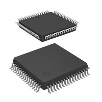
DF71251AD50FPV Renesas Electronics America, DF71251AD50FPV Datasheet - Page 19

DF71251AD50FPV
Manufacturer Part Number
DF71251AD50FPV
Description
MCU RISC FLASH 32K 8K 64LQFP
Manufacturer
Renesas Electronics America
Series
SuperH® SH Tinyr
Datasheet
1.DF71243N50FPV.pdf
(794 pages)
Specifications of DF71251AD50FPV
Core Processor
SH-2
Core Size
32-Bit
Speed
50MHz
Connectivity
SCI
Peripherals
POR, PWM, WDT
Number Of I /o
37
Program Memory Size
32KB (32K x 8)
Program Memory Type
FLASH
Ram Size
8K x 8
Voltage - Supply (vcc/vdd)
4 V ~ 5.5 V
Data Converters
A/D 8x10b
Oscillator Type
External
Operating Temperature
-40°C ~ 85°C
Package / Case
64-LQFP
Lead Free Status / RoHS Status
Lead free / RoHS Compliant
Eeprom Size
-
Available stocks
Company
Part Number
Manufacturer
Quantity
Price
Company:
Part Number:
DF71251AD50FPV
Manufacturer:
Renesas Electronics America
Quantity:
10 000
- Current page: 19 of 794
- Download datasheet (5Mb)
17.8 Supplementary Information ............................................................................................... 631
17.9 Off-Board Programming Mode.......................................................................................... 662
Section 18 RAM ..................................................................................................663
18.1 Usage Notes ....................................................................................................................... 664
Section 19 Power-Down Modes ..........................................................................665
19.1 Features.............................................................................................................................. 665
19.2 Input/Output Pins............................................................................................................... 667
19.3 Register Descriptions ......................................................................................................... 667
19.4 Sleep Mode ........................................................................................................................ 675
19.5 Software Standby Mode..................................................................................................... 676
19.6 Module Standby Mode....................................................................................................... 678
19.7 Usage Note......................................................................................................................... 678
Section 20 List of Registers .................................................................................679
20.1 Register Address Table (In the Order from Lower Addresses).......................................... 680
20.2 Register Bit List ................................................................................................................. 688
20.3 Register States in Each Operating Mode ........................................................................... 702
17.8.1 Specifications of the Standard Serial Communications Interface in Boot Mode.. 631
17.8.2 Areas for Storage of the Procedural Program and Data for Programming............ 658
18.1.1 Module Standby Mode Setting ............................................................................. 664
18.1.2 Address Error........................................................................................................ 664
18.1.3 Initial Values in RAM........................................................................................... 664
19.1.1 Types of Power-Down Modes .............................................................................. 665
19.3.1 Standby Control Register 1 (STBCR1)................................................................. 668
19.3.2 Standby Control Register 2 (STBCR2)................................................................. 669
19.3.3 Standby Control Register 3 (STBCR3)................................................................. 670
19.3.4 Standby Control Register 4 (STBCR4)................................................................. 671
19.3.5 Standby Control Register 5 (STBCR5)................................................................. 672
19.3.6 Standby Control Register 6 (STBCR6)................................................................. 673
19.3.7 RAM Control Register (RAMCR)........................................................................ 674
19.4.1 Transition to Sleep Mode...................................................................................... 675
19.4.2 Canceling Sleep Mode .......................................................................................... 675
19.5.1 Transition to Software Standby Mode .................................................................. 676
19.5.2 Canceling Software Standby Mode....................................................................... 677
19.6.1 Transition to Module Standby Mode .................................................................... 678
19.6.2 Canceling Module Standby Function.................................................................... 678
19.7.1 Current Consumption while Waiting for Oscillation to be Stabilized .................. 678
19.7.2 Executing the SLEEP Instruction ......................................................................... 678
Rev. 5.00 Mar. 06, 2009 Page xvii of xviii
REJ09B0243-0500
Related parts for DF71251AD50FPV
Image
Part Number
Description
Manufacturer
Datasheet
Request
R

Part Number:
Description:
KIT STARTER FOR M16C/29
Manufacturer:
Renesas Electronics America
Datasheet:

Part Number:
Description:
KIT STARTER FOR R8C/2D
Manufacturer:
Renesas Electronics America
Datasheet:

Part Number:
Description:
R0K33062P STARTER KIT
Manufacturer:
Renesas Electronics America
Datasheet:

Part Number:
Description:
KIT STARTER FOR R8C/23 E8A
Manufacturer:
Renesas Electronics America
Datasheet:

Part Number:
Description:
KIT STARTER FOR R8C/25
Manufacturer:
Renesas Electronics America
Datasheet:

Part Number:
Description:
KIT STARTER H8S2456 SHARPE DSPLY
Manufacturer:
Renesas Electronics America
Datasheet:

Part Number:
Description:
KIT STARTER FOR R8C38C
Manufacturer:
Renesas Electronics America
Datasheet:

Part Number:
Description:
KIT STARTER FOR R8C35C
Manufacturer:
Renesas Electronics America
Datasheet:

Part Number:
Description:
KIT STARTER FOR R8CL3AC+LCD APPS
Manufacturer:
Renesas Electronics America
Datasheet:

Part Number:
Description:
KIT STARTER FOR RX610
Manufacturer:
Renesas Electronics America
Datasheet:

Part Number:
Description:
KIT STARTER FOR R32C/118
Manufacturer:
Renesas Electronics America
Datasheet:

Part Number:
Description:
KIT DEV RSK-R8C/26-29
Manufacturer:
Renesas Electronics America
Datasheet:

Part Number:
Description:
KIT STARTER FOR SH7124
Manufacturer:
Renesas Electronics America
Datasheet:

Part Number:
Description:
KIT STARTER FOR H8SX/1622
Manufacturer:
Renesas Electronics America
Datasheet:

Part Number:
Description:
KIT DEV FOR SH7203
Manufacturer:
Renesas Electronics America
Datasheet:


