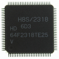
HD64F2318VTE25 Renesas Electronics America, HD64F2318VTE25 Datasheet - Page 20

HD64F2318VTE25
Manufacturer Part Number
HD64F2318VTE25
Description
IC H8S MCU FLASH 256K 100-QFP
Manufacturer
Renesas Electronics America
Series
H8® H8S/2300r
Specifications of HD64F2318VTE25
Core Processor
H8S/2000
Core Size
16-Bit
Speed
25MHz
Connectivity
SCI, SmartCard
Peripherals
POR, PWM, WDT
Number Of I /o
71
Program Memory Size
256KB (256K x 8)
Program Memory Type
FLASH
Ram Size
8K x 8
Voltage - Supply (vcc/vdd)
2.7 V ~ 3.6 V
Data Converters
A/D 8x10b; D/A 2x8b
Oscillator Type
Internal
Operating Temperature
-20°C ~ 75°C
Package / Case
100-TQFP, 100-VQFP
Lead Free Status / RoHS Status
Contains lead / RoHS non-compliant
Eeprom Size
-
- Current page: 20 of 1146
- Download datasheet (7Mb)
5.5
5.6
Section 6 Bus Controller....................................................................................139
6.1
6.2
6.3
6.4
6.5
6.6
Rev.7.00 Feb. 14, 2007 page xviii of xxxii
REJ09B0089-0700
Usage Notes ...................................................................................................................... 134
5.5.1
5.5.2
5.5.3
5.5.4
DTC Activation by Interrupt............................................................................................. 136
5.6.1
5.6.2
5.6.3
Overview........................................................................................................................... 139
6.1.1
6.1.2
6.1.3
6.1.4
Register Descriptions ........................................................................................................ 143
6.2.1
6.2.2
6.2.3
6.2.4
6.2.5
Overview of Bus Control .................................................................................................. 152
6.3.1
6.3.2
6.3.3
6.3.4
6.3.5
Basic Bus Interface ........................................................................................................... 157
6.4.1
6.4.2
6.4.3
6.4.4
6.4.5
Burst ROM Interface......................................................................................................... 170
6.5.1
6.5.2
6.5.3
Idle Cycle .......................................................................................................................... 173
6.6.1
Contention between Interrupt Generation and Disabling..................................... 134
Instructions that Disable Interrupts ...................................................................... 135
Times when Interrupts are Disabled .................................................................... 135
Interrupts during Execution of EEPMOV Instruction.......................................... 135
Overview.............................................................................................................. 136
Block Diagram ..................................................................................................... 136
Operation ............................................................................................................. 137
Features................................................................................................................ 139
Block Diagram ..................................................................................................... 140
Pin Configuration................................................................................................. 141
Register Configuration......................................................................................... 142
Bus Width Control Register (ABWCR)............................................................... 143
Access State Control Register (ASTCR) ............................................................. 144
Wait Control Registers H and L (WCRH, WCRL).............................................. 145
Bus Control Register H (BCRH) ......................................................................... 148
Bus Control Register L (BCRL) .......................................................................... 150
Area Partitioning.................................................................................................. 152
Bus Specifications................................................................................................ 153
Memory Interfaces ............................................................................................... 154
Advanced Mode ................................................................................................... 155
Chip Select Signals .............................................................................................. 156
Overview.............................................................................................................. 157
Data Size and Data Alignment............................................................................. 157
Valid Strobes........................................................................................................ 159
Basic Timing........................................................................................................ 160
Wait Control ........................................................................................................ 168
Overview.............................................................................................................. 170
Basic Timing........................................................................................................ 170
Wait Control ........................................................................................................ 172
Operation ............................................................................................................. 173
Related parts for HD64F2318VTE25
Image
Part Number
Description
Manufacturer
Datasheet
Request
R

Part Number:
Description:
KIT STARTER FOR M16C/29
Manufacturer:
Renesas Electronics America
Datasheet:

Part Number:
Description:
KIT STARTER FOR R8C/2D
Manufacturer:
Renesas Electronics America
Datasheet:

Part Number:
Description:
R0K33062P STARTER KIT
Manufacturer:
Renesas Electronics America
Datasheet:

Part Number:
Description:
KIT STARTER FOR R8C/23 E8A
Manufacturer:
Renesas Electronics America
Datasheet:

Part Number:
Description:
KIT STARTER FOR R8C/25
Manufacturer:
Renesas Electronics America
Datasheet:

Part Number:
Description:
KIT STARTER H8S2456 SHARPE DSPLY
Manufacturer:
Renesas Electronics America
Datasheet:

Part Number:
Description:
KIT STARTER FOR R8C38C
Manufacturer:
Renesas Electronics America
Datasheet:

Part Number:
Description:
KIT STARTER FOR R8C35C
Manufacturer:
Renesas Electronics America
Datasheet:

Part Number:
Description:
KIT STARTER FOR R8CL3AC+LCD APPS
Manufacturer:
Renesas Electronics America
Datasheet:

Part Number:
Description:
KIT STARTER FOR RX610
Manufacturer:
Renesas Electronics America
Datasheet:

Part Number:
Description:
KIT STARTER FOR R32C/118
Manufacturer:
Renesas Electronics America
Datasheet:

Part Number:
Description:
KIT DEV RSK-R8C/26-29
Manufacturer:
Renesas Electronics America
Datasheet:

Part Number:
Description:
KIT STARTER FOR SH7124
Manufacturer:
Renesas Electronics America
Datasheet:

Part Number:
Description:
KIT STARTER FOR H8SX/1622
Manufacturer:
Renesas Electronics America
Datasheet:

Part Number:
Description:
KIT DEV FOR SH7203
Manufacturer:
Renesas Electronics America
Datasheet:


