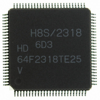
HD64F2318VTE25 Renesas Electronics America, HD64F2318VTE25 Datasheet - Page 780

HD64F2318VTE25
Manufacturer Part Number
HD64F2318VTE25
Description
IC H8S MCU FLASH 256K 100-QFP
Manufacturer
Renesas Electronics America
Series
H8® H8S/2300r
Specifications of HD64F2318VTE25
Core Processor
H8S/2000
Core Size
16-Bit
Speed
25MHz
Connectivity
SCI, SmartCard
Peripherals
POR, PWM, WDT
Number Of I /o
71
Program Memory Size
256KB (256K x 8)
Program Memory Type
FLASH
Ram Size
8K x 8
Voltage - Supply (vcc/vdd)
2.7 V ~ 3.6 V
Data Converters
A/D 8x10b; D/A 2x8b
Oscillator Type
Internal
Operating Temperature
-20°C ~ 75°C
Package / Case
100-TQFP, 100-VQFP
Lead Free Status / RoHS Status
Contains lead / RoHS non-compliant
Eeprom Size
-
- Current page: 780 of 1146
- Download datasheet (7Mb)
Section 17 ROM
4. Monitoring runaway by WDT
17.28
Along with its on-board programming mode, this LSI also has a PROM mode as a further mode
for the writing and erasing of programs and data. In the PROM mode, a general-purpose PROM
programmer can freely be used to write programs to the on-chip ROM. Program/erase is possible
on the user MAT and user boot MAT. The PROM programmer must support Renesas Technology
microcomputers with 512-kbyte flash memory units as a device type.
A status-polling system is adopted for operation in automatic program, automatic erase, and
status-read modes. In the status-read mode, details of the system's internal signals are output after
execution of automatic programming or automatic erasure. In the PROM mode, provide a 12-MHz
input-clock signal.
Table 17.56 PROM Mode Pins
Pin Names
Mode pins: MD2, MD1, MD0
Mode setting pins: PF2, PF1, PF0
STBY pin
RES pin
XTAL, EXTAL pins
Other pins requiring setting: P23, P25
Rev.7.00 Feb. 14, 2007 page 746 of 1108
REJ09B0089-0700
Unlike the conventional F-ZTAT H8S microcomputer, no countermeasures are available for a
runaway by WDT during programming/erasing by the downloaded on-chip program.
Prepare countermeasures (e.g. use of the user branch routine and periodic timer interrupts) for
WDT while taking the programming/erasing time into consideration as required.
PROM Mode
Settings/External Circuit Connection
Low level input to MD2, MD1, and MD0
High level input to PF2, low level input to PF1 and PF0
High-level input (do not select hardware standby mode)
Reset circuit
Oscillator circuit
High-level input to P23, low-level input to P25
Related parts for HD64F2318VTE25
Image
Part Number
Description
Manufacturer
Datasheet
Request
R

Part Number:
Description:
KIT STARTER FOR M16C/29
Manufacturer:
Renesas Electronics America
Datasheet:

Part Number:
Description:
KIT STARTER FOR R8C/2D
Manufacturer:
Renesas Electronics America
Datasheet:

Part Number:
Description:
R0K33062P STARTER KIT
Manufacturer:
Renesas Electronics America
Datasheet:

Part Number:
Description:
KIT STARTER FOR R8C/23 E8A
Manufacturer:
Renesas Electronics America
Datasheet:

Part Number:
Description:
KIT STARTER FOR R8C/25
Manufacturer:
Renesas Electronics America
Datasheet:

Part Number:
Description:
KIT STARTER H8S2456 SHARPE DSPLY
Manufacturer:
Renesas Electronics America
Datasheet:

Part Number:
Description:
KIT STARTER FOR R8C38C
Manufacturer:
Renesas Electronics America
Datasheet:

Part Number:
Description:
KIT STARTER FOR R8C35C
Manufacturer:
Renesas Electronics America
Datasheet:

Part Number:
Description:
KIT STARTER FOR R8CL3AC+LCD APPS
Manufacturer:
Renesas Electronics America
Datasheet:

Part Number:
Description:
KIT STARTER FOR RX610
Manufacturer:
Renesas Electronics America
Datasheet:

Part Number:
Description:
KIT STARTER FOR R32C/118
Manufacturer:
Renesas Electronics America
Datasheet:

Part Number:
Description:
KIT DEV RSK-R8C/26-29
Manufacturer:
Renesas Electronics America
Datasheet:

Part Number:
Description:
KIT STARTER FOR SH7124
Manufacturer:
Renesas Electronics America
Datasheet:

Part Number:
Description:
KIT STARTER FOR H8SX/1622
Manufacturer:
Renesas Electronics America
Datasheet:

Part Number:
Description:
KIT DEV FOR SH7203
Manufacturer:
Renesas Electronics America
Datasheet:


