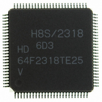
HD64F2318VTE25 Renesas Electronics America, HD64F2318VTE25 Datasheet - Page 31

HD64F2318VTE25
Manufacturer Part Number
HD64F2318VTE25
Description
IC H8S MCU FLASH 256K 100-QFP
Manufacturer
Renesas Electronics America
Series
H8® H8S/2300r
Specifications of HD64F2318VTE25
Core Processor
H8S/2000
Core Size
16-Bit
Speed
25MHz
Connectivity
SCI, SmartCard
Peripherals
POR, PWM, WDT
Number Of I /o
71
Program Memory Size
256KB (256K x 8)
Program Memory Type
FLASH
Ram Size
8K x 8
Voltage - Supply (vcc/vdd)
2.7 V ~ 3.6 V
Data Converters
A/D 8x10b; D/A 2x8b
Oscillator Type
Internal
Operating Temperature
-20°C ~ 75°C
Package / Case
100-TQFP, 100-VQFP
Lead Free Status / RoHS Status
Contains lead / RoHS non-compliant
Eeprom Size
-
- Current page: 31 of 1146
- Download datasheet (7Mb)
17.26 Flash Memory Emulation in RAM ................................................................................... 741
17.27 Switching between User MAT and User Boot MAT ........................................................ 744
17.28 PROM Mode..................................................................................................................... 746
17.29 Further Information........................................................................................................... 754
Section 18 Clock Pulse Generator .....................................................................793
18.1 Overview........................................................................................................................... 793
18.2 Register Descriptions ........................................................................................................ 794
18.3 Oscillator........................................................................................................................... 796
18.4 Duty Adjustment Circuit ................................................................................................... 800
18.5 Medium-Speed Clock Divider .......................................................................................... 800
18.6 Bus Master Clock Selection Circuit .................................................................................. 800
Section 19 Power-Down Modes ........................................................................801
19.1 Overview........................................................................................................................... 801
19.2 Register Descriptions ........................................................................................................ 803
17.25.1 Hardware Protection ............................................................................................ 738
17.25.2 Software Protection.............................................................................................. 739
17.25.3 Error Protection.................................................................................................... 739
17.27.1 Usage Notes ......................................................................................................... 745
17.28.1 Pin Arrangement of the Socket Adapter .............................................................. 747
17.28.2 PROM Mode Operation....................................................................................... 749
17.28.3 Memory-Read Mode............................................................................................ 750
17.28.4 Auto-Program Mode ............................................................................................ 751
17.28.5 Auto-Erase Mode ................................................................................................. 751
17.28.6 Status-Read Mode................................................................................................ 752
17.28.7 Status Polling ....................................................................................................... 752
17.28.8 Time Taken in Transition to PROM Mode .......................................................... 753
17.28.9 Notes on Using PROM Mode .............................................................................. 753
17.29.1 Serial Communication Interface Specification for Boot Mode............................ 754
17.29.2 AC Characteristics and Timing in PROM Mode ................................................. 781
17.29.3 Procedure Program and Storable Area for Programming Data ............................ 787
18.1.1 Block Diagram ..................................................................................................... 793
18.1.2 Register Configuration......................................................................................... 794
18.2.1 System Clock Control Register (SCKCR) ........................................................... 794
18.3.1 Connecting a Crystal Resonator........................................................................... 796
18.3.2 External Clock Input ............................................................................................ 798
19.1.1 Register Configuration......................................................................................... 802
19.2.1 Standby Control Register (SBYCR) .................................................................... 803
19.2.2 System Clock Control Register (SCKCR) ........................................................... 805
Rev.7.00 Feb. 14, 2007 page xxix of xxxii
REJ09B0089-0700
Related parts for HD64F2318VTE25
Image
Part Number
Description
Manufacturer
Datasheet
Request
R

Part Number:
Description:
KIT STARTER FOR M16C/29
Manufacturer:
Renesas Electronics America
Datasheet:

Part Number:
Description:
KIT STARTER FOR R8C/2D
Manufacturer:
Renesas Electronics America
Datasheet:

Part Number:
Description:
R0K33062P STARTER KIT
Manufacturer:
Renesas Electronics America
Datasheet:

Part Number:
Description:
KIT STARTER FOR R8C/23 E8A
Manufacturer:
Renesas Electronics America
Datasheet:

Part Number:
Description:
KIT STARTER FOR R8C/25
Manufacturer:
Renesas Electronics America
Datasheet:

Part Number:
Description:
KIT STARTER H8S2456 SHARPE DSPLY
Manufacturer:
Renesas Electronics America
Datasheet:

Part Number:
Description:
KIT STARTER FOR R8C38C
Manufacturer:
Renesas Electronics America
Datasheet:

Part Number:
Description:
KIT STARTER FOR R8C35C
Manufacturer:
Renesas Electronics America
Datasheet:

Part Number:
Description:
KIT STARTER FOR R8CL3AC+LCD APPS
Manufacturer:
Renesas Electronics America
Datasheet:

Part Number:
Description:
KIT STARTER FOR RX610
Manufacturer:
Renesas Electronics America
Datasheet:

Part Number:
Description:
KIT STARTER FOR R32C/118
Manufacturer:
Renesas Electronics America
Datasheet:

Part Number:
Description:
KIT DEV RSK-R8C/26-29
Manufacturer:
Renesas Electronics America
Datasheet:

Part Number:
Description:
KIT STARTER FOR SH7124
Manufacturer:
Renesas Electronics America
Datasheet:

Part Number:
Description:
KIT STARTER FOR H8SX/1622
Manufacturer:
Renesas Electronics America
Datasheet:

Part Number:
Description:
KIT DEV FOR SH7203
Manufacturer:
Renesas Electronics America
Datasheet:


