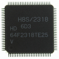
HD64F2318VTE25 Renesas Electronics America, HD64F2318VTE25 Datasheet - Page 24

HD64F2318VTE25
Manufacturer Part Number
HD64F2318VTE25
Description
IC H8S MCU FLASH 256K 100-QFP
Manufacturer
Renesas Electronics America
Series
H8® H8S/2300r
Specifications of HD64F2318VTE25
Core Processor
H8S/2000
Core Size
16-Bit
Speed
25MHz
Connectivity
SCI, SmartCard
Peripherals
POR, PWM, WDT
Number Of I /o
71
Program Memory Size
256KB (256K x 8)
Program Memory Type
FLASH
Ram Size
8K x 8
Voltage - Supply (vcc/vdd)
2.7 V ~ 3.6 V
Data Converters
A/D 8x10b; D/A 2x8b
Oscillator Type
Internal
Operating Temperature
-20°C ~ 75°C
Package / Case
100-TQFP, 100-VQFP
Lead Free Status / RoHS Status
Contains lead / RoHS non-compliant
Eeprom Size
-
- Current page: 24 of 1146
- Download datasheet (7Mb)
9.5
9.6
9.7
Section 10 8-Bit Timers.....................................................................................391
10.1 Overview........................................................................................................................... 391
10.2 Register Descriptions ........................................................................................................ 394
10.3 Operation........................................................................................................................... 401
10.4 Interrupts ........................................................................................................................... 406
10.5 Sample Application........................................................................................................... 407
10.6 Usage Notes ...................................................................................................................... 408
Rev.7.00 Feb. 14, 2007 page xxii of xxxii
REJ09B0089-0700
9.4.3
9.4.4
9.4.5
9.4.6
9.4.7
Interrupts ........................................................................................................................... 369
9.5.1
9.5.2
9.5.3
Operation Timing.............................................................................................................. 372
9.6.1
9.6.2
Usage Notes ...................................................................................................................... 380
10.1.1 Features................................................................................................................ 391
10.1.2 Block Diagram ..................................................................................................... 392
10.1.3 Pin Configuration................................................................................................. 393
10.1.4 Register Configuration......................................................................................... 393
10.2.1 Timer Counters 0 and 1 (TCNT0, TCNT1) ......................................................... 394
10.2.2 Time Constant Registers A0 and A1 (TCORA0, TCORA1) ............................... 394
10.2.3 Time Constant Registers B0 and B1 (TCORB0, TCORB1) ................................ 395
10.2.4 Time Control Registers 0 and 1 (TCR0, TCR1) .................................................. 395
10.2.5 Timer Control/Status Registers 0 and 1 (TCSR0, TCSR1).................................. 397
10.2.6 Module Stop Control Register (MSTPCR) .......................................................... 400
10.3.1 TCNT Incrementation Timing ............................................................................. 401
10.3.2 Compare Match Timing ....................................................................................... 402
10.3.3 Timing of TCNT External Reset.......................................................................... 404
10.3.4 Timing of Overflow Flag (OVF) Setting ............................................................. 404
10.3.5 Operation with Cascaded Connection .................................................................. 405
10.4.1 Interrupt Sources and DTC Activation ................................................................ 406
10.4.2 A/D Converter Activation.................................................................................... 406
10.6.1 Contention between TCNT Write and Clear........................................................ 408
10.6.2 Contention between TCNT Write and Increment ................................................ 409
Synchronous Operation........................................................................................ 349
Buffer Operation .................................................................................................. 351
Cascaded Operation ............................................................................................. 355
PWM Modes ........................................................................................................ 357
Phase Counting Mode .......................................................................................... 363
Interrupt Sources and Priorities............................................................................ 369
DTC Activation.................................................................................................... 371
A/D Converter Activation.................................................................................... 371
Input/Output Timing ............................................................................................ 372
Interrupt Signal Timing........................................................................................ 376
Related parts for HD64F2318VTE25
Image
Part Number
Description
Manufacturer
Datasheet
Request
R

Part Number:
Description:
KIT STARTER FOR M16C/29
Manufacturer:
Renesas Electronics America
Datasheet:

Part Number:
Description:
KIT STARTER FOR R8C/2D
Manufacturer:
Renesas Electronics America
Datasheet:

Part Number:
Description:
R0K33062P STARTER KIT
Manufacturer:
Renesas Electronics America
Datasheet:

Part Number:
Description:
KIT STARTER FOR R8C/23 E8A
Manufacturer:
Renesas Electronics America
Datasheet:

Part Number:
Description:
KIT STARTER FOR R8C/25
Manufacturer:
Renesas Electronics America
Datasheet:

Part Number:
Description:
KIT STARTER H8S2456 SHARPE DSPLY
Manufacturer:
Renesas Electronics America
Datasheet:

Part Number:
Description:
KIT STARTER FOR R8C38C
Manufacturer:
Renesas Electronics America
Datasheet:

Part Number:
Description:
KIT STARTER FOR R8C35C
Manufacturer:
Renesas Electronics America
Datasheet:

Part Number:
Description:
KIT STARTER FOR R8CL3AC+LCD APPS
Manufacturer:
Renesas Electronics America
Datasheet:

Part Number:
Description:
KIT STARTER FOR RX610
Manufacturer:
Renesas Electronics America
Datasheet:

Part Number:
Description:
KIT STARTER FOR R32C/118
Manufacturer:
Renesas Electronics America
Datasheet:

Part Number:
Description:
KIT DEV RSK-R8C/26-29
Manufacturer:
Renesas Electronics America
Datasheet:

Part Number:
Description:
KIT STARTER FOR SH7124
Manufacturer:
Renesas Electronics America
Datasheet:

Part Number:
Description:
KIT STARTER FOR H8SX/1622
Manufacturer:
Renesas Electronics America
Datasheet:

Part Number:
Description:
KIT DEV FOR SH7203
Manufacturer:
Renesas Electronics America
Datasheet:


