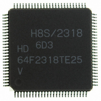
HD64F2318VTE25 Renesas Electronics America, HD64F2318VTE25 Datasheet - Page 30

HD64F2318VTE25
Manufacturer Part Number
HD64F2318VTE25
Description
IC H8S MCU FLASH 256K 100-QFP
Manufacturer
Renesas Electronics America
Series
H8® H8S/2300r
Specifications of HD64F2318VTE25
Core Processor
H8S/2000
Core Size
16-Bit
Speed
25MHz
Connectivity
SCI, SmartCard
Peripherals
POR, PWM, WDT
Number Of I /o
71
Program Memory Size
256KB (256K x 8)
Program Memory Type
FLASH
Ram Size
8K x 8
Voltage - Supply (vcc/vdd)
2.7 V ~ 3.6 V
Data Converters
A/D 8x10b; D/A 2x8b
Oscillator Type
Internal
Operating Temperature
-20°C ~ 75°C
Package / Case
100-TQFP, 100-VQFP
Lead Free Status / RoHS Status
Contains lead / RoHS non-compliant
Eeprom Size
-
- Current page: 30 of 1146
- Download datasheet (7Mb)
17.17 Flash Memory Protection.................................................................................................. 662
17.18 Flash Memory Emulation in RAM ................................................................................... 666
17.19 Interrupt Handling when Programming/Erasing Flash Memory....................................... 668
17.20 Flash Memory Programmer Mode .................................................................................... 669
17.21 Flash Memory Programming and Erasing Precautions ..................................................... 684
17.22 Overview of Flash Memory (H8S/2319C 0.18µm F-ZTAT)............................................ 686
17.23 Register Description of Flash Memory ............................................................................. 697
17.24 On-Board Programming Mode ......................................................................................... 720
17.25 Protection .......................................................................................................................... 738
Rev.7.00 Feb. 14, 2007 page xxviii of xxxii
REJ09B0089-0700
17.17.1 Hardware Protection ............................................................................................ 662
17.17.2 Software Protection.............................................................................................. 663
17.17.3 Error Protection.................................................................................................... 664
17.18.1 Emulation in RAM............................................................................................... 666
17.18.2 RAM Overlap ...................................................................................................... 667
17.20.1 Programmer Mode Setting ................................................................................... 669
17.20.2 Socket Adapters and Memory Map...................................................................... 670
17.20.3 Programmer Mode Operation .............................................................................. 672
17.20.4 Memory Read Mode ............................................................................................ 673
17.20.5 Auto-Program Mode ............................................................................................ 677
17.20.6 Auto-Erase Mode ................................................................................................. 679
17.20.7 Status Read Mode ................................................................................................ 680
17.20.8 Status Polling ....................................................................................................... 681
17.20.9 Programmer Mode Transition Time..................................................................... 682
17.20.10 Notes on Memory Programming........................................................................ 682
17.22.1 Features................................................................................................................ 686
17.22.2 Overview.............................................................................................................. 688
17.22.3 Operating Mode of Flash Memory....................................................................... 689
17.22.4 Mode Comparison................................................................................................ 690
17.22.5 Flash MAT Configuration.................................................................................... 691
17.22.6 Block Division ..................................................................................................... 692
17.22.7 Programming/Erasing Interface ........................................................................... 693
17.22.8 Pin Configuration................................................................................................. 695
17.22.9 Register Configuration......................................................................................... 695
17.23.1 Programming/Erasing Interface Register ............................................................. 697
17.23.2 Programming/Erasing Interface Parameter .......................................................... 704
17.23.3 System Control Register 2 (SYSCR2) ................................................................. 717
17.23.4 RAM Emulation Register (RAMER)................................................................... 718
17.24.1 Boot Mode ........................................................................................................... 720
17.24.2 User Program Mode............................................................................................. 724
17.24.3 User Boot Mode................................................................................................... 734
Related parts for HD64F2318VTE25
Image
Part Number
Description
Manufacturer
Datasheet
Request
R

Part Number:
Description:
KIT STARTER FOR M16C/29
Manufacturer:
Renesas Electronics America
Datasheet:

Part Number:
Description:
KIT STARTER FOR R8C/2D
Manufacturer:
Renesas Electronics America
Datasheet:

Part Number:
Description:
R0K33062P STARTER KIT
Manufacturer:
Renesas Electronics America
Datasheet:

Part Number:
Description:
KIT STARTER FOR R8C/23 E8A
Manufacturer:
Renesas Electronics America
Datasheet:

Part Number:
Description:
KIT STARTER FOR R8C/25
Manufacturer:
Renesas Electronics America
Datasheet:

Part Number:
Description:
KIT STARTER H8S2456 SHARPE DSPLY
Manufacturer:
Renesas Electronics America
Datasheet:

Part Number:
Description:
KIT STARTER FOR R8C38C
Manufacturer:
Renesas Electronics America
Datasheet:

Part Number:
Description:
KIT STARTER FOR R8C35C
Manufacturer:
Renesas Electronics America
Datasheet:

Part Number:
Description:
KIT STARTER FOR R8CL3AC+LCD APPS
Manufacturer:
Renesas Electronics America
Datasheet:

Part Number:
Description:
KIT STARTER FOR RX610
Manufacturer:
Renesas Electronics America
Datasheet:

Part Number:
Description:
KIT STARTER FOR R32C/118
Manufacturer:
Renesas Electronics America
Datasheet:

Part Number:
Description:
KIT DEV RSK-R8C/26-29
Manufacturer:
Renesas Electronics America
Datasheet:

Part Number:
Description:
KIT STARTER FOR SH7124
Manufacturer:
Renesas Electronics America
Datasheet:

Part Number:
Description:
KIT STARTER FOR H8SX/1622
Manufacturer:
Renesas Electronics America
Datasheet:

Part Number:
Description:
KIT DEV FOR SH7203
Manufacturer:
Renesas Electronics America
Datasheet:


