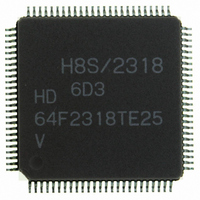
HD64F2318VTE25 Renesas Electronics America, HD64F2318VTE25 Datasheet - Page 439

HD64F2318VTE25
Manufacturer Part Number
HD64F2318VTE25
Description
IC H8S MCU FLASH 256K 100-QFP
Manufacturer
Renesas Electronics America
Series
H8® H8S/2300r
Specifications of HD64F2318VTE25
Core Processor
H8S/2000
Core Size
16-Bit
Speed
25MHz
Connectivity
SCI, SmartCard
Peripherals
POR, PWM, WDT
Number Of I /o
71
Program Memory Size
256KB (256K x 8)
Program Memory Type
FLASH
Ram Size
8K x 8
Voltage - Supply (vcc/vdd)
2.7 V ~ 3.6 V
Data Converters
A/D 8x10b; D/A 2x8b
Oscillator Type
Internal
Operating Temperature
-20°C ~ 75°C
Package / Case
100-TQFP, 100-VQFP
Lead Free Status / RoHS Status
Contains lead / RoHS non-compliant
Eeprom Size
-
- Current page: 439 of 1146
- Download datasheet (7Mb)
10.3.5
If bits CKS2 to CKS0 in either TCR0 or TCR1 are set to B'100, the 8-bit timers of the two
channels are cascaded. With this configuration, a single 16-bit timer could be used (16-bit counter
mode) or compare matches of the 8-bit channel 0 could be counted by the timer of channel 1
(compare match counter mode). In this case, the timer operates as below.
16-Bit Counter Mode: When bits CKS2 to CKS0 in TCR0 are set to B'100, the timer functions as
a single 16-bit timer with channel 0 occupying the upper 8 bits and channel 1 occupying the lower
8 bits.
• Setting of compare match flags
• Counter clear specification
• Pin output
Compare Match Counter Mode: When bits CKS2 to CKS0 in TCR1 are B'100, TCNT1 counts
compare match A’s for channel 0.
Channels 0 and 1 are controlled independently. Conditions such as setting of the CMF flag,
generation of interrupts, output from the TMO pin, and counter clear are in accordance with the
settings for each channel.
Usage Note: If the 16-bit counter mode and compare match counter mode are set simultaneously,
the input clock pulses for TCNT0 and TCNT1 are not generated and thus the counters will stop
operating. Software should therefore avoid using both these modes.
⎯ The CMF flag in TCSR0 is set to 1 when a 16-bit compare match event occurs.
⎯ The CMF flag in TCSR1 is set to 1 when a lower 8-bit compare match event occurs.
⎯ If the CCLR1 and CCLR0 bits in TCR0 have been set for counter clear at compare match,
⎯ The settings of the CCLR1 and CCLR0 bits in TCR1 are ignored. The lower 8 bits cannot
⎯ Control of output from the TMO0 pin by bits OS3 to OS0 in TCSR0 is in accordance with
⎯ Control of output from the TMO1 pin by bits OS3 to OS0 in TCSR1 is in accordance with
the 16-bit counter (TCNT0 and TCNT1 together) is cleared when a 16-bit compare match
event occurs. The 16-bit counter (TCNT0 and TCNT1 together) is cleared even if counter
clear by the TMRI0 pin has also been set.
be cleared independently.
the 16-bit compare match conditions.
the lower 8-bit compare match conditions.
Operation with Cascaded Connection
Rev.7.00 Feb. 14, 2007 page 405 of 1108
Section 10 8-Bit Timers
REJ09B0089-0700
Related parts for HD64F2318VTE25
Image
Part Number
Description
Manufacturer
Datasheet
Request
R

Part Number:
Description:
KIT STARTER FOR M16C/29
Manufacturer:
Renesas Electronics America
Datasheet:

Part Number:
Description:
KIT STARTER FOR R8C/2D
Manufacturer:
Renesas Electronics America
Datasheet:

Part Number:
Description:
R0K33062P STARTER KIT
Manufacturer:
Renesas Electronics America
Datasheet:

Part Number:
Description:
KIT STARTER FOR R8C/23 E8A
Manufacturer:
Renesas Electronics America
Datasheet:

Part Number:
Description:
KIT STARTER FOR R8C/25
Manufacturer:
Renesas Electronics America
Datasheet:

Part Number:
Description:
KIT STARTER H8S2456 SHARPE DSPLY
Manufacturer:
Renesas Electronics America
Datasheet:

Part Number:
Description:
KIT STARTER FOR R8C38C
Manufacturer:
Renesas Electronics America
Datasheet:

Part Number:
Description:
KIT STARTER FOR R8C35C
Manufacturer:
Renesas Electronics America
Datasheet:

Part Number:
Description:
KIT STARTER FOR R8CL3AC+LCD APPS
Manufacturer:
Renesas Electronics America
Datasheet:

Part Number:
Description:
KIT STARTER FOR RX610
Manufacturer:
Renesas Electronics America
Datasheet:

Part Number:
Description:
KIT STARTER FOR R32C/118
Manufacturer:
Renesas Electronics America
Datasheet:

Part Number:
Description:
KIT DEV RSK-R8C/26-29
Manufacturer:
Renesas Electronics America
Datasheet:

Part Number:
Description:
KIT STARTER FOR SH7124
Manufacturer:
Renesas Electronics America
Datasheet:

Part Number:
Description:
KIT STARTER FOR H8SX/1622
Manufacturer:
Renesas Electronics America
Datasheet:

Part Number:
Description:
KIT DEV FOR SH7203
Manufacturer:
Renesas Electronics America
Datasheet:


