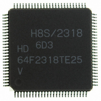
HD64F2318VTE25 Renesas Electronics America, HD64F2318VTE25 Datasheet - Page 546

HD64F2318VTE25
Manufacturer Part Number
HD64F2318VTE25
Description
IC H8S MCU FLASH 256K 100-QFP
Manufacturer
Renesas Electronics America
Series
H8® H8S/2300r
Specifications of HD64F2318VTE25
Core Processor
H8S/2000
Core Size
16-Bit
Speed
25MHz
Connectivity
SCI, SmartCard
Peripherals
POR, PWM, WDT
Number Of I /o
71
Program Memory Size
256KB (256K x 8)
Program Memory Type
FLASH
Ram Size
8K x 8
Voltage - Supply (vcc/vdd)
2.7 V ~ 3.6 V
Data Converters
A/D 8x10b; D/A 2x8b
Oscillator Type
Internal
Operating Temperature
-20°C ~ 75°C
Package / Case
100-TQFP, 100-VQFP
Lead Free Status / RoHS Status
Contains lead / RoHS non-compliant
Eeprom Size
-
- Current page: 546 of 1146
- Download datasheet (7Mb)
Section 13 Smart Card Interface
The operation sequence is as follows.
[1] When the data line is not in use it is in the high-impedance state, and is fixed high with a pull-
[2] The transmitting station starts transfer of one frame of data. The data frame starts with a start
[3] With the smart card interface, the data line then returns to the high-impedance state. The data
[4] The receiving station carries out a parity check.
[5] If the transmitting station does not receive an error signal, it proceeds to transmit the next data
Block Transfer Mode: The operation sequence in block transfer mode is as follows.
[1] When the data line is not in use it is in the high-impedance state, and is fixed high with a pull-
[2] The transmitting station starts transfer of one frame of data. The data frame starts with a start
[3] With the smart card interface, the data line then returns to the high-impedance state. The data
[4] The receiving station carries out a parity check, but does not output an error signal even if an
[5] The transmitting station proceeds to transmit the next data frame.
Rev.7.00 Feb. 14, 2007 page 512 of 1108
REJ09B0089-0700
up resistor.
bit (Ds, low-level), followed by 8 data bits (D0 to D7) and a parity bit (Dp).
line is pulled high with a pull-up resistor.
If there is no parity error and the data is received normally, the receiving station waits for
reception of the next data.
If a parity error occurs, however, the receiving station outputs an error signal (DE, low-level)
to request retransmission of the data. After outputting the error signal for the prescribed length
of time, the receiving station places the signal line in the high-impedance state again. The
signal line is pulled high again by a pull-up resistor.
frame.
If it does receive an error signal, however, it returns to step [2] and retransmits the data in
which the error occurred.
up resistor.
bit (Ds, low-level), followed by 8 data bits (D0 to D7) and a parity bit (Dp).
line is pulled high with a pull-up resistor.
error has occurred. Since subsequent receive operations cannot be carried out if an error
occurs, the error flag must be cleared to 0 before the parity bit for the next frame is received.
Related parts for HD64F2318VTE25
Image
Part Number
Description
Manufacturer
Datasheet
Request
R

Part Number:
Description:
KIT STARTER FOR M16C/29
Manufacturer:
Renesas Electronics America
Datasheet:

Part Number:
Description:
KIT STARTER FOR R8C/2D
Manufacturer:
Renesas Electronics America
Datasheet:

Part Number:
Description:
R0K33062P STARTER KIT
Manufacturer:
Renesas Electronics America
Datasheet:

Part Number:
Description:
KIT STARTER FOR R8C/23 E8A
Manufacturer:
Renesas Electronics America
Datasheet:

Part Number:
Description:
KIT STARTER FOR R8C/25
Manufacturer:
Renesas Electronics America
Datasheet:

Part Number:
Description:
KIT STARTER H8S2456 SHARPE DSPLY
Manufacturer:
Renesas Electronics America
Datasheet:

Part Number:
Description:
KIT STARTER FOR R8C38C
Manufacturer:
Renesas Electronics America
Datasheet:

Part Number:
Description:
KIT STARTER FOR R8C35C
Manufacturer:
Renesas Electronics America
Datasheet:

Part Number:
Description:
KIT STARTER FOR R8CL3AC+LCD APPS
Manufacturer:
Renesas Electronics America
Datasheet:

Part Number:
Description:
KIT STARTER FOR RX610
Manufacturer:
Renesas Electronics America
Datasheet:

Part Number:
Description:
KIT STARTER FOR R32C/118
Manufacturer:
Renesas Electronics America
Datasheet:

Part Number:
Description:
KIT DEV RSK-R8C/26-29
Manufacturer:
Renesas Electronics America
Datasheet:

Part Number:
Description:
KIT STARTER FOR SH7124
Manufacturer:
Renesas Electronics America
Datasheet:

Part Number:
Description:
KIT STARTER FOR H8SX/1622
Manufacturer:
Renesas Electronics America
Datasheet:

Part Number:
Description:
KIT DEV FOR SH7203
Manufacturer:
Renesas Electronics America
Datasheet:


