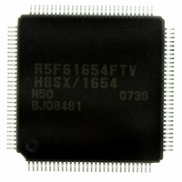
DF61654N50FTV Renesas Electronics America, DF61654N50FTV Datasheet - Page 14

DF61654N50FTV
Manufacturer Part Number
DF61654N50FTV
Description
IC H8SX/1654 MCU FLASH 120TQFP
Manufacturer
Renesas Electronics America
Series
H8® H8SX/1600r
Datasheet
1.DF61653N50FTV.pdf
(1020 pages)
Specifications of DF61654N50FTV
Core Processor
H8SX
Core Size
32-Bit
Speed
50MHz
Connectivity
I²C, IrDA, SCI, SmartCard, USB
Peripherals
DMA, PWM, WDT
Number Of I /o
75
Program Memory Size
512KB (512K x 8)
Program Memory Type
FLASH
Ram Size
40K x 8
Voltage - Supply (vcc/vdd)
3 V ~ 3.6 V
Data Converters
A/D 8x10b; D/A 2x8b
Oscillator Type
External
Operating Temperature
-20°C ~ 75°C
Package / Case
120-TQFP, 120-VQFP
For Use With
HS0005KCU11H - EMULATOR E10A-USB H8S(X),SH2(A)3DK1657 - DEV EVAL KIT FOR H8SX/1657
Lead Free Status / RoHS Status
Lead free / RoHS Compliant
Eeprom Size
-
Available stocks
Company
Part Number
Manufacturer
Quantity
Price
Company:
Part Number:
DF61654N50FTV
Manufacturer:
Renesas Electronics America
Quantity:
10 000
- Current page: 14 of 1020
- Download datasheet (6Mb)
Section 6 Bus Controller (BSC) ........................................................................ 125
6.1
6.2
6.3
6.4
6.5
6.6
6.7
Rev.1.00 Sep. 08, 2005 Page xii of xlviii
5.8.5
5.8.6
Features.............................................................................................................................. 125
Register Descriptions......................................................................................................... 128
6.2.1
6.2.2
6.2.3
6.2.4
6.2.5
6.2.6
6.2.7
6.2.8
6.2.9
6.2.10 SRAM Mode Control Register (SRAMCR) ......................................................... 146
6.2.11 Burst ROM Interface Control Register (BROMCR) ............................................ 147
6.2.12 Address/Data Multiplexed I/O Control Register (MPXCR) ................................. 149
Bus Configuration.............................................................................................................. 150
Multi-Clock Function and Number of Access Cycles ....................................................... 151
External Bus....................................................................................................................... 155
6.5.1
6.5.2
6.5.3
6.5.4
6.5.5
6.5.6
Basic Bus Interface ............................................................................................................ 172
6.6.1
6.6.2
6.6.3
6.6.4
6.6.5
6.6.6
6.6.7
Byte Control SRAM Interface ........................................................................................... 185
6.7.1
6.7.2
6.7.3
6.7.4
Interrupts during Execution of MOVMD and MOVSD Instructions.................... 123
Interrupts of Peripheral Modules .......................................................................... 124
Bus Width Control Register (ABWCR) ............................................................... 129
Access State Control Register (ASTCR) .............................................................. 130
Wait Control Registers A and B (WTCRA, WTCRB) ......................................... 131
Read Strobe Timing Control Register (RDNCR) ................................................. 136
CS Assertion Period Control Registers (CSACR) ................................................ 137
Idle Control Register (IDLCR) ............................................................................. 140
Bus Control Register 1 (BCR1) ............................................................................ 142
Bus Control Register 2 (BCR2) ............................................................................ 144
Endian Control Register (ENDIANCR) ............................................................... 145
Input/Output Pins.................................................................................................. 155
Area Division........................................................................................................ 158
Chip Select Signals ............................................................................................... 159
External Bus Interface .......................................................................................... 160
Area and External Bus Interface ........................................................................... 164
Endian and Data Alignment.................................................................................. 169
Data Bus ............................................................................................................... 172
I/O Pins Used for Basic Bus Interface .................................................................. 172
Basic Timing......................................................................................................... 173
Wait Control ......................................................................................................... 179
Read Strobe (RD) Timing..................................................................................... 181
Extension of Chip Select (CS) Assertion Period .................................................. 182
DACK Signal Output Timing ............................................................................... 184
Byte Control SRAM Space Setting....................................................................... 185
Data Bus ............................................................................................................... 185
I/O Pins Used for Byte Control SRAM Interface ................................................. 186
Basic Timing......................................................................................................... 187
Related parts for DF61654N50FTV
Image
Part Number
Description
Manufacturer
Datasheet
Request
R

Part Number:
Description:
KIT STARTER FOR M16C/29
Manufacturer:
Renesas Electronics America
Datasheet:

Part Number:
Description:
KIT STARTER FOR R8C/2D
Manufacturer:
Renesas Electronics America
Datasheet:

Part Number:
Description:
R0K33062P STARTER KIT
Manufacturer:
Renesas Electronics America
Datasheet:

Part Number:
Description:
KIT STARTER FOR R8C/23 E8A
Manufacturer:
Renesas Electronics America
Datasheet:

Part Number:
Description:
KIT STARTER FOR R8C/25
Manufacturer:
Renesas Electronics America
Datasheet:

Part Number:
Description:
KIT STARTER H8S2456 SHARPE DSPLY
Manufacturer:
Renesas Electronics America
Datasheet:

Part Number:
Description:
KIT STARTER FOR R8C38C
Manufacturer:
Renesas Electronics America
Datasheet:

Part Number:
Description:
KIT STARTER FOR R8C35C
Manufacturer:
Renesas Electronics America
Datasheet:

Part Number:
Description:
KIT STARTER FOR R8CL3AC+LCD APPS
Manufacturer:
Renesas Electronics America
Datasheet:

Part Number:
Description:
KIT STARTER FOR RX610
Manufacturer:
Renesas Electronics America
Datasheet:

Part Number:
Description:
KIT STARTER FOR R32C/118
Manufacturer:
Renesas Electronics America
Datasheet:

Part Number:
Description:
KIT DEV RSK-R8C/26-29
Manufacturer:
Renesas Electronics America
Datasheet:

Part Number:
Description:
KIT STARTER FOR SH7124
Manufacturer:
Renesas Electronics America
Datasheet:

Part Number:
Description:
KIT STARTER FOR H8SX/1622
Manufacturer:
Renesas Electronics America
Datasheet:

Part Number:
Description:
KIT DEV FOR SH7203
Manufacturer:
Renesas Electronics America
Datasheet:


