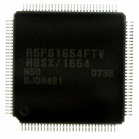
DF61654N50FTV Renesas Electronics America, DF61654N50FTV Datasheet - Page 44

DF61654N50FTV
Manufacturer Part Number
DF61654N50FTV
Description
IC H8SX/1654 MCU FLASH 120TQFP
Manufacturer
Renesas Electronics America
Series
H8® H8SX/1600r
Datasheet
1.DF61653N50FTV.pdf
(1020 pages)
Specifications of DF61654N50FTV
Core Processor
H8SX
Core Size
32-Bit
Speed
50MHz
Connectivity
I²C, IrDA, SCI, SmartCard, USB
Peripherals
DMA, PWM, WDT
Number Of I /o
75
Program Memory Size
512KB (512K x 8)
Program Memory Type
FLASH
Ram Size
40K x 8
Voltage - Supply (vcc/vdd)
3 V ~ 3.6 V
Data Converters
A/D 8x10b; D/A 2x8b
Oscillator Type
External
Operating Temperature
-20°C ~ 75°C
Package / Case
120-TQFP, 120-VQFP
For Use With
HS0005KCU11H - EMULATOR E10A-USB H8S(X),SH2(A)3DK1657 - DEV EVAL KIT FOR H8SX/1657
Lead Free Status / RoHS Status
Lead free / RoHS Compliant
Eeprom Size
-
Available stocks
Company
Part Number
Manufacturer
Quantity
Price
Company:
Part Number:
DF61654N50FTV
Manufacturer:
Renesas Electronics America
Quantity:
10 000
- Current page: 44 of 1020
- Download datasheet (6Mb)
Section 5 Interrupt Controller
Table 5.1
Table 5.2
Table 5.3
Table 5.4
Table 5.5
Table 5.6
Table 5.7
Table 5.8
Section 6 Bus Controller (BSC)
Table 6.1
Table 6.2
Table 6.3
Table 6.4
Table 6.5
Table 6.6
Table 6.7
Table 6.8
Table 6.9
Table 6.10
Table 6.11
Table 6.12
Table 6.13
Table 6.14
Table 6.15
Table 6.16
Table 6.17
Table 6.18
Table 6.19
Table 6.20
Table 6.21
Table 6.22
Table 6.23
Table 6.24
Table 6.25
Table 6.26
Section 7 DMA Controller (DMAC)
Table 7.1
Table 7.2
Rev.1.00 Sep. 08, 2005 Page xlii of xlviii
Pin Configuration.................................................................................................... 89
Interrupt Sources, Vector Address Offsets, and Interrupt Priority........................ 105
Interrupt Control Modes ....................................................................................... 110
Interrupt Response Times ..................................................................................... 115
Number of Execution States in Interrupt Handling Routine ................................. 116
Interrupt Source Selection and Clear Control ....................................................... 118
CPU Priority Control ............................................................................................ 120
Example of Priority Control Function Setting and Control State ......................... 121
Synchronization Clocks and Their Corresponding Functions............................... 151
Pin Configuration.................................................................................................. 155
Pin Functions in Each Interface ............................................................................ 157
Interface Names and Area Names......................................................................... 160
Areas Specifiable for Each Interface .................................................................... 161
Number of Access Cycles..................................................................................... 163
Area 0 External Interface...................................................................................... 164
Area 1 External Interface...................................................................................... 165
Area 2 External Interface...................................................................................... 165
Area 3 External Interface...................................................................................... 166
Area 4 External Interface...................................................................................... 166
Area 5 External Interface...................................................................................... 167
Area 6 External Interface...................................................................................... 168
Area 7 External Interface...................................................................................... 168
I/O Pins for Basic Bus Interface ........................................................................... 172
I/O Pins for Byte Control SRAM Interface .......................................................... 186
I/O Pins Used for Burst ROM Interface................................................................ 194
Address/Data Multiplex........................................................................................ 198
I/O Pins for Address/Data Multiplexed I/O Interface ........................................... 199
Number of Idle Cycle Insertion Selection in Each Area....................................... 209
Number of Idle Cycle Insertions........................................................................... 209
Idle Cycles in Mixed Accesses to Normal Space.................................................. 216
Pin States in Idle Cycle......................................................................................... 217
Pin States in Bus Released State........................................................................... 219
Number of Access Cycles for On-Chip Memory Spaces...................................... 221
Number of Access Cycles for Registers of On-Chip Peripheral Modules ............ 221
Pin Configuration.................................................................................................. 232
Data Access Size, Valid Bits, and Settable Size ................................................... 239
Related parts for DF61654N50FTV
Image
Part Number
Description
Manufacturer
Datasheet
Request
R

Part Number:
Description:
KIT STARTER FOR M16C/29
Manufacturer:
Renesas Electronics America
Datasheet:

Part Number:
Description:
KIT STARTER FOR R8C/2D
Manufacturer:
Renesas Electronics America
Datasheet:

Part Number:
Description:
R0K33062P STARTER KIT
Manufacturer:
Renesas Electronics America
Datasheet:

Part Number:
Description:
KIT STARTER FOR R8C/23 E8A
Manufacturer:
Renesas Electronics America
Datasheet:

Part Number:
Description:
KIT STARTER FOR R8C/25
Manufacturer:
Renesas Electronics America
Datasheet:

Part Number:
Description:
KIT STARTER H8S2456 SHARPE DSPLY
Manufacturer:
Renesas Electronics America
Datasheet:

Part Number:
Description:
KIT STARTER FOR R8C38C
Manufacturer:
Renesas Electronics America
Datasheet:

Part Number:
Description:
KIT STARTER FOR R8C35C
Manufacturer:
Renesas Electronics America
Datasheet:

Part Number:
Description:
KIT STARTER FOR R8CL3AC+LCD APPS
Manufacturer:
Renesas Electronics America
Datasheet:

Part Number:
Description:
KIT STARTER FOR RX610
Manufacturer:
Renesas Electronics America
Datasheet:

Part Number:
Description:
KIT STARTER FOR R32C/118
Manufacturer:
Renesas Electronics America
Datasheet:

Part Number:
Description:
KIT DEV RSK-R8C/26-29
Manufacturer:
Renesas Electronics America
Datasheet:

Part Number:
Description:
KIT STARTER FOR SH7124
Manufacturer:
Renesas Electronics America
Datasheet:

Part Number:
Description:
KIT STARTER FOR H8SX/1622
Manufacturer:
Renesas Electronics America
Datasheet:

Part Number:
Description:
KIT DEV FOR SH7203
Manufacturer:
Renesas Electronics America
Datasheet:


