DF61654N50FTV Renesas Electronics America, DF61654N50FTV Datasheet - Page 45
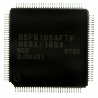
DF61654N50FTV
Manufacturer Part Number
DF61654N50FTV
Description
IC H8SX/1654 MCU FLASH 120TQFP
Manufacturer
Renesas Electronics America
Series
H8® H8SX/1600r
Datasheet
1.DF61653N50FTV.pdf
(1020 pages)
Specifications of DF61654N50FTV
Core Processor
H8SX
Core Size
32-Bit
Speed
50MHz
Connectivity
I²C, IrDA, SCI, SmartCard, USB
Peripherals
DMA, PWM, WDT
Number Of I /o
75
Program Memory Size
512KB (512K x 8)
Program Memory Type
FLASH
Ram Size
40K x 8
Voltage - Supply (vcc/vdd)
3 V ~ 3.6 V
Data Converters
A/D 8x10b; D/A 2x8b
Oscillator Type
External
Operating Temperature
-20°C ~ 75°C
Package / Case
120-TQFP, 120-VQFP
For Use With
HS0005KCU11H - EMULATOR E10A-USB H8S(X),SH2(A)3DK1657 - DEV EVAL KIT FOR H8SX/1657
Lead Free Status / RoHS Status
Lead free / RoHS Compliant
Eeprom Size
-
Available stocks
Company
Part Number
Manufacturer
Quantity
Price
Company:

Part Number:
DF61654N50FTV
Manufacturer:
Renesas Electronics America
Quantity:
10 000


Table 7.3
Table 7.4
Table 7.5
Table 7.6
Table 7.7
Section 8 Data Transfer Controller (DTC)
Table 8.1
Table 8.2
Table 8.3
Table 8.4
Table 8.5
Table 8.6
Table 8.7
Table 8.8
Table 8.9
Table 8.10
Section 9 I/O Ports
Table 9.1
Table 9.2
Table 9.3
Table 9.4
Table 9.5
Section 10 16-Bit Timer Pulse Unit (TPU)
Table 10.1
Table 10.2
Table 10.3
Table 10.4
Table 10.5
Table 10.6
Table 10.7
Table 10.8
Table 10.9
Table 10.10
Table 10.11
Table 10.12
Table 10.13
Table 10.14
Table 10.15
Settings and Areas of Extended Repeat Area ....................................................... 253
Transfer Modes ..................................................................................................... 254
List of On-chip module interrupts to DMAC........................................................ 265
Priority among DMAC Channels.......................................................................... 280
Interrupt Sources and Priority............................................................................... 302
Interrupt Sources, DTC Vector Addresses, and Corresponding DTCEs............... 319
DTC Transfer Modes ............................................................................................ 321
Chain Transfer Conditions.................................................................................... 323
Number of Bus Cycle Divisions and Access Size................................................. 323
Transfer Information Writeback Skip Condition
and Writeback Skipped Registers ......................................................................... 326
Register Function in Normal Transfer Mode ........................................................ 326
Register Function in Repeat Transfer Mode ......................................................... 328
Register Function in Block Transfer Mode........................................................... 329
DTC Execution Status........................................................................................... 333
Number of Cycles Required for Each Execution State ......................................... 334
Port Functions ....................................................................................................... 341
Register Configuration in Each Port ..................................................................... 347
Startup Mode and Initial Value............................................................................. 348
Input Pull-Up MOS State...................................................................................... 351
Available Output Signals and Settings in Each Port ............................................. 378
TPU Functions ...................................................................................................... 396
Pin Configuration.................................................................................................. 399
CCLR2 to CCLR0 (Channels 0 and 3) ................................................................. 403
CCLR2 to CCLR0 (Channels 1, 2, 4, and 5) ........................................................ 404
Input Clock Edge Selection .................................................................................. 404
TPSC2 to TPSC0 (Channel 0) .............................................................................. 405
TPSC2 to TPSC0 (Channel 1) .............................................................................. 405
TPSC2 to TPSC0 (Channel 2) .............................................................................. 406
TPSC2 to TPSC0 (Channel 3) .............................................................................. 406
TPSC2 to TPSC0 (Channel 4) .......................................................................... 407
TPSC2 to TPSC0 (Channel 5) .......................................................................... 407
MD3 to MD0 .................................................................................................... 409
TIORH_0 .......................................................................................................... 411
TIORL_0........................................................................................................... 412
TIOR_1 ............................................................................................................. 413
Rev.1.00 Sep. 08, 2005 Page xliii of xlviii
Related parts for DF61654N50FTV
Image
Part Number
Description
Manufacturer
Datasheet
Request
R

Part Number:
Description:
KIT STARTER FOR M16C/29
Manufacturer:
Renesas Electronics America
Datasheet:

Part Number:
Description:
KIT STARTER FOR R8C/2D
Manufacturer:
Renesas Electronics America
Datasheet:

Part Number:
Description:
R0K33062P STARTER KIT
Manufacturer:
Renesas Electronics America
Datasheet:

Part Number:
Description:
KIT STARTER FOR R8C/23 E8A
Manufacturer:
Renesas Electronics America
Datasheet:

Part Number:
Description:
KIT STARTER FOR R8C/25
Manufacturer:
Renesas Electronics America
Datasheet:

Part Number:
Description:
KIT STARTER H8S2456 SHARPE DSPLY
Manufacturer:
Renesas Electronics America
Datasheet:

Part Number:
Description:
KIT STARTER FOR R8C38C
Manufacturer:
Renesas Electronics America
Datasheet:

Part Number:
Description:
KIT STARTER FOR R8C35C
Manufacturer:
Renesas Electronics America
Datasheet:

Part Number:
Description:
KIT STARTER FOR R8CL3AC+LCD APPS
Manufacturer:
Renesas Electronics America
Datasheet:
Part Number:
Description:
KIT STARTER FOR RX610
Manufacturer:
Renesas Electronics America
Datasheet:

Part Number:
Description:
KIT STARTER FOR R32C/118
Manufacturer:
Renesas Electronics America
Datasheet:

Part Number:
Description:
KIT DEV RSK-R8C/26-29
Manufacturer:
Renesas Electronics America
Datasheet:

Part Number:
Description:
KIT STARTER FOR SH7124
Manufacturer:
Renesas Electronics America
Datasheet:

Part Number:
Description:
KIT STARTER FOR H8SX/1622
Manufacturer:
Renesas Electronics America
Datasheet:

Part Number:
Description:
KIT DEV FOR SH7203
Manufacturer:
Renesas Electronics America
Datasheet: