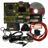
R0K572030S000BE Renesas Electronics America, R0K572030S000BE Datasheet - Page 1666

R0K572030S000BE
Manufacturer Part Number
R0K572030S000BE
Description
KIT DEV FOR SH7203
Manufacturer
Renesas Electronics America
Series
Renesas Starter Kits (RSK)r
Type
MCUr
Specifications of R0K572030S000BE
Contents
CPU Board, LCD Module, E10A-Lite Emulator, Cable, QuickStart Guide and CD-ROM
Silicon Manufacturer
Renesas
Kit Contents
Board
Silicon Family Name
SH7203
Silicon Core Number
R5S72030W200FP
Tool / Board Applications
General Purpose MCU, MPU, DSP, DSC
Mcu Supported Families
SH7203
Lead Free Status / RoHS Status
Contains lead / RoHS non-compliant
For Use With/related Products
SH7203
Lead Free Status / Rohs Status
Compliant
- Current page: 1666 of 1686
- Download datasheet (10Mb)
Rev. 3.00 Sep. 28, 2009 Page 1634 of 1650
REJ09B0313-0300
Item
28.3.2 Software Standby
Mode
(2) Canceling Software
Standby Mode
28.3.4 Deep Standby
Mode
(2) Canceling Deep
Standby Mode
Page
1425
1431
Revision (See Manual for Details)
Description amended
•
…After the elapse of the time set in the clock select bits
(CKS[2:0]) in the watchdog timer control/status register
(WTCSR) of the WDT before the transition to software
standby mode, the WDT overflow occurs. Since this overflow
indicates that the clock has been stabilized, the clock pulse
will be supplied to the entire chip after this overflow. Software
standby mode is thus cleared and NMI interrupt exception
handling (IRQ interrupt exception handling in case of IRRQ)
is started. If the priority level of the generated interrupt is
equal to or lower than the interrupt mask level specified in the
status register (SR) of the CPU, the interrupt request is not
accepted and software standby mode is not canceled.
Description amended
•
When the falling edge or rising edge of the NMI pin (selected
by the NMI edge select bit (NMIE) in interrupt control register
0 (ICR0) of the interrupt controller (INTC)) or the falling edge
or rising edge of an IRQ pin (IRQ7 to IRQ0 assigned to PE11
to PE4) (selected by the IRQn sense select bits (IRQn1S and
IRQn0S) in interrupt control register 1 (ICR1) of the interrupt
controller (INTC)) is detected, clock oscillation is started after
the wait time for the oscillation settling time. After the
oscillation settling time has elapsed, deep standby mode is
cancelled and the power-on reset exception handling is
executed. If the priority level of the generated interrupt is
equal to or lower than the interrupt mask level specified in the
status register (SR) of the CPU, the interrupt request is not
accepted and deep standby mode is not canceled.
… (The same applies to the IRQ pin.)
In addition, the pin levels of the NMI pin and all interrupt pins
(IRQ) selected to cancel deep standby mode (by settings in
the deep standby mode cancelation source select register)
should be as follows during the transition to deep standby
mode, regardless of whether or not those pins are actually
used to cancel deep standby mode:
Canceling by an interrupt
Canceling by an interrupt
⎯ Pins set to cancel deep standby mode at their rising
⎯ Pins set to cancel deep standby mode at their falling
edge should be low during the transition.
edge should be high during the transition.
Related parts for R0K572030S000BE
Image
Part Number
Description
Manufacturer
Datasheet
Request
R

Part Number:
Description:
KIT STARTER FOR M16C/29
Manufacturer:
Renesas Electronics America
Datasheet:

Part Number:
Description:
KIT STARTER FOR R8C/2D
Manufacturer:
Renesas Electronics America
Datasheet:

Part Number:
Description:
R0K33062P STARTER KIT
Manufacturer:
Renesas Electronics America
Datasheet:

Part Number:
Description:
KIT STARTER FOR R8C/23 E8A
Manufacturer:
Renesas Electronics America
Datasheet:

Part Number:
Description:
KIT STARTER FOR R8C/25
Manufacturer:
Renesas Electronics America
Datasheet:

Part Number:
Description:
KIT STARTER H8S2456 SHARPE DSPLY
Manufacturer:
Renesas Electronics America
Datasheet:

Part Number:
Description:
KIT STARTER FOR R8C38C
Manufacturer:
Renesas Electronics America
Datasheet:

Part Number:
Description:
KIT STARTER FOR R8C35C
Manufacturer:
Renesas Electronics America
Datasheet:

Part Number:
Description:
KIT STARTER FOR R8CL3AC+LCD APPS
Manufacturer:
Renesas Electronics America
Datasheet:

Part Number:
Description:
KIT STARTER FOR RX610
Manufacturer:
Renesas Electronics America
Datasheet:

Part Number:
Description:
KIT STARTER FOR R32C/118
Manufacturer:
Renesas Electronics America
Datasheet:

Part Number:
Description:
KIT DEV RSK-R8C/26-29
Manufacturer:
Renesas Electronics America
Datasheet:

Part Number:
Description:
KIT STARTER FOR SH7124
Manufacturer:
Renesas Electronics America
Datasheet:

Part Number:
Description:
KIT STARTER FOR H8SX/1622
Manufacturer:
Renesas Electronics America
Datasheet:

Part Number:
Description:
KIT STARTER FOR R8C/18191A1B
Manufacturer:
Renesas Electronics America
Datasheet:


