LFEBS12UB Freescale Semiconductor, LFEBS12UB Datasheet - Page 1222
LFEBS12UB
Manufacturer Part Number
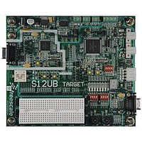
LFEBS12UB
Description
KIT STUDENT LEARNING S12 DG128
Manufacturer
Freescale Semiconductor
Specifications of LFEBS12UB
Architecture
8/16-bit
Code Gen Tools Included
Code Warrior
Silicon Manufacturer
Freescale
Core Architecture
S12
Core Sub-architecture
S12
Silicon Core Number
MC9S12
Silicon Family Name
S12D
Kit Contents
HCS12 DG128 Learning Kit
Rohs Compliant
Yes
Lead Free Status / RoHS Status
Lead free / RoHS Compliant


Appendix A Electrical Characteristics
A.2.2.1
PortAD output drivers switching can adversely affect the ATD accuracy whilst converting the analog
voltage on other PortAD pins because the output drivers are supplied from the VDDA/VSSA ATD supply
pins. Although internal design measures are implemented to minimize the affect of output driver noise, it
is recommended to configure PortAD pins as outputs only for low frequency, low load outputs. The impact
on ATD accuracy is load dependent and not specified. The values specified are valid under condition that
no PortAD output drivers switch during conversion.
A.2.2.2
Due to the input pin leakage current as specified in
there will be a voltage drop from the signal source to the ATD input. The maximum source resistance R
specifies results in an error (10-bit resolution) of less than 1/2 LSB (2.5 mV) at the maximum leakage
current. If device or operating conditions are less than worst case or leakage-induced error is acceptable,
larger values of source resistance of up to 10Kohm are allowed.
A.2.2.3
When sampling an additional internal capacitor is switched to the input. This can cause a voltage drop due
to charge sharing with the external and the pin capacitance. For a maximum sampling error of the input
voltage ≤ 1LSB (10-bit resolution), then the external filter capacitor, C
A.2.2.4
There are two cases to consider.
1222
1. A current is injected into the channel being converted. The channel being stressed has conversion
2. Current is injected into pins in the neighborhood of the channel being converted. A portion of this
values of $3FF (in 10-bit mode) for analog inputs greater than V
V
current is picked up by the channel (coupling ratio K), This additional current impacts the accuracy
of the conversion depending on the source resistance.
RL
unless the current is higher than specified as disruptive condition.
Port AD Output Drivers Switching
Source Resistance
Source Capacitance
Current Injection
MC9S12XE-Family Reference Manual , Rev. 1.23
Table A-8
in conjunction with the source resistance
f
≥ 1024 * (C
RH
and $000 for values less than
INS
Freescale Semiconductor
–C
INN
).
S
Related parts for LFEBS12UB
Image
Part Number
Description
Manufacturer
Datasheet
Request
R

Part Number:
Description:
Manufacturer:
Freescale Semiconductor, Inc
Datasheet:
Part Number:
Description:
Manufacturer:
Freescale Semiconductor, Inc
Datasheet:
Part Number:
Description:
Manufacturer:
Freescale Semiconductor, Inc
Datasheet:
Part Number:
Description:
Manufacturer:
Freescale Semiconductor, Inc
Datasheet:
Part Number:
Description:
Manufacturer:
Freescale Semiconductor, Inc
Datasheet:
Part Number:
Description:
Manufacturer:
Freescale Semiconductor, Inc
Datasheet:
Part Number:
Description:
Manufacturer:
Freescale Semiconductor, Inc
Datasheet:
Part Number:
Description:
Manufacturer:
Freescale Semiconductor, Inc
Datasheet:
Part Number:
Description:
Manufacturer:
Freescale Semiconductor, Inc
Datasheet:
Part Number:
Description:
Manufacturer:
Freescale Semiconductor, Inc
Datasheet:
Part Number:
Description:
Manufacturer:
Freescale Semiconductor, Inc
Datasheet:
Part Number:
Description:
Manufacturer:
Freescale Semiconductor, Inc
Datasheet:
Part Number:
Description:
Manufacturer:
Freescale Semiconductor, Inc
Datasheet:
Part Number:
Description:
Manufacturer:
Freescale Semiconductor, Inc
Datasheet:
Part Number:
Description:
Manufacturer:
Freescale Semiconductor, Inc
Datasheet: