LFEBS12UB Freescale Semiconductor, LFEBS12UB Datasheet - Page 1223
LFEBS12UB
Manufacturer Part Number
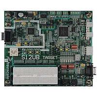
LFEBS12UB
Description
KIT STUDENT LEARNING S12 DG128
Manufacturer
Freescale Semiconductor
Specifications of LFEBS12UB
Architecture
8/16-bit
Code Gen Tools Included
Code Warrior
Silicon Manufacturer
Freescale
Core Architecture
S12
Core Sub-architecture
S12
Silicon Core Number
MC9S12
Silicon Family Name
S12D
Kit Contents
HCS12 DG128 Learning Kit
Rohs Compliant
Yes
Lead Free Status / RoHS Status
Lead free / RoHS Compliant


1
A.2.3
Table A-17
injection, input capacitance and source resistance.
A.2.3.1
For the following definitions see also
Differential non-linearity (DNL) is defined as the difference between two adjacent switching steps.
The integral non-linearity (INL) is defined as the sum of all DNLs:
Freescale Semiconductor
Conditions are shown in
Num C
Refer to A.2.2.2 for further information concerning source resistance
1
2
3
4
5
6
C Max input source resistance
D Total input capacitance Non sampling
D Input internal Resistance
C Disruptive analog input current
C Coupling ratio positive current injection
C Coupling ratio negative current injection
The additional input voltage error on the converted channel can be calculated as:
with I
Total input capacitance Sampling
and
ATD Accuracy
INJ
ATD Accuracy Definitions
V
Table A-18
being the sum of the currents injected into the two pins adjacent to the converted channel.
ERR
Table A-4
= K * R
specify the ATD conversion performance excluding any errors due to current
S
unless otherwise noted
Rating
* I
MC9S12XE-Family Reference Manual Rev. 1.23
Table A-16. ATD Electrical Characteristics
1
INJ
INL n ( )
Figure
DNL i ( )
=
i
A-1.
∑
=
n
1
=
DNL i ( )
V
------------------------- - 1
i
1LSB
–
V
i 1
=
–
Symbol
V
-------------------- - n
1LSB
C
C
R
n
I
–
R
K
K
NA
INN
INS
INA
–
S
p
n
V
0
–
–2.5
Min
—
—
—
—
—
—
Appendix A Electrical Characteristics
Typ
—
—
—
—
—
—
5
1E-4
2E-3
Max
2.5
10
16
15
1
Unit
A/A
A/A
mA
KΩ
kΩ
pF
1223
Related parts for LFEBS12UB
Image
Part Number
Description
Manufacturer
Datasheet
Request
R

Part Number:
Description:
Manufacturer:
Freescale Semiconductor, Inc
Datasheet:
Part Number:
Description:
Manufacturer:
Freescale Semiconductor, Inc
Datasheet:
Part Number:
Description:
Manufacturer:
Freescale Semiconductor, Inc
Datasheet:
Part Number:
Description:
Manufacturer:
Freescale Semiconductor, Inc
Datasheet:
Part Number:
Description:
Manufacturer:
Freescale Semiconductor, Inc
Datasheet:
Part Number:
Description:
Manufacturer:
Freescale Semiconductor, Inc
Datasheet:
Part Number:
Description:
Manufacturer:
Freescale Semiconductor, Inc
Datasheet:
Part Number:
Description:
Manufacturer:
Freescale Semiconductor, Inc
Datasheet:
Part Number:
Description:
Manufacturer:
Freescale Semiconductor, Inc
Datasheet:
Part Number:
Description:
Manufacturer:
Freescale Semiconductor, Inc
Datasheet:
Part Number:
Description:
Manufacturer:
Freescale Semiconductor, Inc
Datasheet:
Part Number:
Description:
Manufacturer:
Freescale Semiconductor, Inc
Datasheet:
Part Number:
Description:
Manufacturer:
Freescale Semiconductor, Inc
Datasheet:
Part Number:
Description:
Manufacturer:
Freescale Semiconductor, Inc
Datasheet:
Part Number:
Description:
Manufacturer:
Freescale Semiconductor, Inc
Datasheet: