LFEBS12UB Freescale Semiconductor, LFEBS12UB Datasheet - Page 610
LFEBS12UB
Manufacturer Part Number
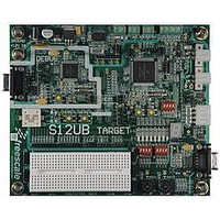
LFEBS12UB
Description
KIT STUDENT LEARNING S12 DG128
Manufacturer
Freescale Semiconductor
Specifications of LFEBS12UB
Architecture
8/16-bit
Code Gen Tools Included
Code Warrior
Silicon Manufacturer
Freescale
Core Architecture
S12
Core Sub-architecture
S12
Silicon Core Number
MC9S12
Silicon Family Name
S12D
Kit Contents
HCS12 DG128 Learning Kit
Rohs Compliant
Yes
Lead Free Status / RoHS Status
Lead free / RoHS Compliant


Chapter 16 Freescale’s Scalable Controller Area Network (S12MSCANV3)
16.2
The MSCAN uses two external pins.
16.2.1
RXCAN is the MSCAN receiver input pin.
16.2.2
TXCAN is the MSCAN transmitter output pin. The TXCAN output pin represents the logic level on the
CAN bus:
16.2.3
A typical CAN system with MSCAN is shown in
to the CAN bus lines through a transceiver device. The transceiver is capable of driving the large current
needed for the CAN bus and has current protection against defective CAN or defective stations.
610
External Signal Description
0 = Dominant state
1 = Recessive state
RXCAN — CAN Receiver Input Pin
TXCAN — CAN Transmitter Output Pin
CAN System
On MCUs with an integrated CAN physical interface (transceiver) the
MSCAN interface is connected internally to the transceiver interface. In
these cases the external availability of signals TXCAN and RXCAN is
optional.
TXCAN
CANH
CAN Controller
Transceiver
CAN node 1
(MSCAN)
MCU
MC9S12XE-Family Reference Manual , Rev. 1.23
CANL
RXCAN
Figure 16-2. CAN System
CAN Bus
NOTE
Figure
CAN node 2
16-2. Each CAN station is connected physically
CAN node n
Freescale Semiconductor
Related parts for LFEBS12UB
Image
Part Number
Description
Manufacturer
Datasheet
Request
R

Part Number:
Description:
Manufacturer:
Freescale Semiconductor, Inc
Datasheet:
Part Number:
Description:
Manufacturer:
Freescale Semiconductor, Inc
Datasheet:
Part Number:
Description:
Manufacturer:
Freescale Semiconductor, Inc
Datasheet:
Part Number:
Description:
Manufacturer:
Freescale Semiconductor, Inc
Datasheet:
Part Number:
Description:
Manufacturer:
Freescale Semiconductor, Inc
Datasheet:
Part Number:
Description:
Manufacturer:
Freescale Semiconductor, Inc
Datasheet:
Part Number:
Description:
Manufacturer:
Freescale Semiconductor, Inc
Datasheet:
Part Number:
Description:
Manufacturer:
Freescale Semiconductor, Inc
Datasheet:
Part Number:
Description:
Manufacturer:
Freescale Semiconductor, Inc
Datasheet:
Part Number:
Description:
Manufacturer:
Freescale Semiconductor, Inc
Datasheet:
Part Number:
Description:
Manufacturer:
Freescale Semiconductor, Inc
Datasheet:
Part Number:
Description:
Manufacturer:
Freescale Semiconductor, Inc
Datasheet:
Part Number:
Description:
Manufacturer:
Freescale Semiconductor, Inc
Datasheet:
Part Number:
Description:
Manufacturer:
Freescale Semiconductor, Inc
Datasheet:
Part Number:
Description:
Manufacturer:
Freescale Semiconductor, Inc
Datasheet: