LFEBS12UB Freescale Semiconductor, LFEBS12UB Datasheet - Page 595
LFEBS12UB
Manufacturer Part Number
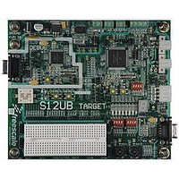
LFEBS12UB
Description
KIT STUDENT LEARNING S12 DG128
Manufacturer
Freescale Semiconductor
Specifications of LFEBS12UB
Architecture
8/16-bit
Code Gen Tools Included
Code Warrior
Silicon Manufacturer
Freescale
Core Architecture
S12
Core Sub-architecture
S12
Silicon Core Number
MC9S12
Silicon Family Name
S12D
Kit Contents
HCS12 DG128 Learning Kit
Rohs Compliant
Yes
Lead Free Status / RoHS Status
Lead free / RoHS Compliant


15.3.1.6
This register contains the variables used in general call and in ten-bit address.
Read and write anytime
15.4
This section provides a complete functional description of the IICV3.
15.4.1
The IIC bus system uses a serial data line (SDA) and a serial clock line (SCL) for data transfer. All devices
connected to it must have open drain or open collector outputs. Logic AND function is exercised on both
lines with external pull-up resistors. The value of these resistors is system dependent.
Normally, a standard communication is composed of four parts: START signal, slave address transmission,
data transfer and STOP signal. They are described briefly in the following sections and illustrated in
Figure
Freescale Semiconductor
RESERVED
Because of an order from the United States International Trade Commission, BGA-packaged product lines and partnumbers
ADR[10:8]
ADTYPE
Reset
GCEN
indicated here currently are not available from Freescale for import or sale in the United States prior to September 2010
Field
5,4,3
2:0
7
6
W
R
15-10.
Module Base + 0x0005
Functional Description
GCEN
General Call Enable.
0 General call is disabled. The module dont receive any general call data and address.
1 enable general call. It indicates that the module can receive address and any data.
Address Type— This bit selects the address length. The variable must be configured correctly before IIC enters
slave mode.
0 7-bit address
1 10-bit address
Reserved — Bit 5,4 and 3 of the IBCR2 are reserved for future compatibility. These bits will always read 0.
Slave Address [10:8] —These 3 bits represent the MSB of the 10-bit address when address type is asserted
(ADTYPE = 1).
I-Bus Protocol
IIC Control Register 2(IBCR2)
0
7
ADTYPE
0
6
Figure 15-9. IIC Bus Control Register 2(IBCR2)
MC9S12XE-Family Reference Manual Rev. 1.23
Table 15-10. IBCR2 Field Descriptions
5
0
0
0
0
4
Description
Chapter 15 Inter-Integrated Circuit (IICV3) Block Description
0
0
3
ADR10
2
0
ADR9
0
1
ADR8
0
0
595
Related parts for LFEBS12UB
Image
Part Number
Description
Manufacturer
Datasheet
Request
R

Part Number:
Description:
Manufacturer:
Freescale Semiconductor, Inc
Datasheet:
Part Number:
Description:
Manufacturer:
Freescale Semiconductor, Inc
Datasheet:
Part Number:
Description:
Manufacturer:
Freescale Semiconductor, Inc
Datasheet:
Part Number:
Description:
Manufacturer:
Freescale Semiconductor, Inc
Datasheet:
Part Number:
Description:
Manufacturer:
Freescale Semiconductor, Inc
Datasheet:
Part Number:
Description:
Manufacturer:
Freescale Semiconductor, Inc
Datasheet:
Part Number:
Description:
Manufacturer:
Freescale Semiconductor, Inc
Datasheet:
Part Number:
Description:
Manufacturer:
Freescale Semiconductor, Inc
Datasheet:
Part Number:
Description:
Manufacturer:
Freescale Semiconductor, Inc
Datasheet:
Part Number:
Description:
Manufacturer:
Freescale Semiconductor, Inc
Datasheet:
Part Number:
Description:
Manufacturer:
Freescale Semiconductor, Inc
Datasheet:
Part Number:
Description:
Manufacturer:
Freescale Semiconductor, Inc
Datasheet:
Part Number:
Description:
Manufacturer:
Freescale Semiconductor, Inc
Datasheet:
Part Number:
Description:
Manufacturer:
Freescale Semiconductor, Inc
Datasheet:
Part Number:
Description:
Manufacturer:
Freescale Semiconductor, Inc
Datasheet: