LFEBS12UB Freescale Semiconductor, LFEBS12UB Datasheet - Page 693
LFEBS12UB
Manufacturer Part Number
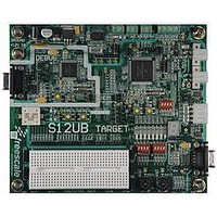
LFEBS12UB
Description
KIT STUDENT LEARNING S12 DG128
Manufacturer
Freescale Semiconductor
Specifications of LFEBS12UB
Architecture
8/16-bit
Code Gen Tools Included
Code Warrior
Silicon Manufacturer
Freescale
Core Architecture
S12
Core Sub-architecture
S12
Silicon Core Number
MC9S12
Silicon Family Name
S12D
Kit Contents
HCS12 DG128 Learning Kit
Rohs Compliant
Yes
Lead Free Status / RoHS Status
Lead free / RoHS Compliant


Chapter 19
Pulse-Width Modulator (S12PWM8B8CV1)
19.1
The PWM definition is based on the HC12 PWM definitions. It contains the basic features from the HC11
with some of the enhancements incorporated on the HC12: center aligned output mode and four available
clock sources.The PWM module has eight channels with independent control of left and center aligned
outputs on each channel.
Each of the eight channels has a programmable period and duty cycle as well as a dedicated counter. A
flexible clock select scheme allows a total of four different clock sources to be used with the counters. Each
of the modulators can create independent continuous waveforms with software-selectable duty rates from
0% to 100%. The PWM outputs can be programmed as left aligned outputs or center aligned outputs.
19.1.1
The PWM block includes these distinctive features:
Freescale Semiconductor
Revision
Because of an order from the United States International Trade Commission, BGA-packaged product lines and partnumbers
Number
V01.17
indicated here currently are not available from Freescale for import or sale in the United States prior to September 2010
•
•
•
•
•
•
•
•
•
•
Eight independent PWM channels with programmable period and duty cycle
Dedicated counter for each PWM channel
Programmable PWM enable/disable for each channel
Software selection of PWM duty pulse polarity for each channel
Period and duty cycle are double buffered. Change takes effect when the end of the effective period
is reached (PWM counter reaches zero) or when the channel is disabled.
Programmable center or left aligned outputs on individual channels
Eight 8-bit channel or four 16-bit channel PWM resolution
Four clock sources (A, B, SA, and SB) provide for a wide range of frequencies
Programmable clock select logic
Emergency shutdown
Introduction
Revision Date
Features
08-01-2004
19.3.2.15/19-
19.6/19-723
Sections
Affected
MC9S12XE-Family Reference Manual , Rev. 1.23
710
Table 19-1.
- Added clarification of PWMIF operation in STOP and WAIT mode.
- Added notes on minimum pulse width of emergency shutdown signal.
Revision History
Description of Changes
693
Related parts for LFEBS12UB
Image
Part Number
Description
Manufacturer
Datasheet
Request
R

Part Number:
Description:
Manufacturer:
Freescale Semiconductor, Inc
Datasheet:
Part Number:
Description:
Manufacturer:
Freescale Semiconductor, Inc
Datasheet:
Part Number:
Description:
Manufacturer:
Freescale Semiconductor, Inc
Datasheet:
Part Number:
Description:
Manufacturer:
Freescale Semiconductor, Inc
Datasheet:
Part Number:
Description:
Manufacturer:
Freescale Semiconductor, Inc
Datasheet:
Part Number:
Description:
Manufacturer:
Freescale Semiconductor, Inc
Datasheet:
Part Number:
Description:
Manufacturer:
Freescale Semiconductor, Inc
Datasheet:
Part Number:
Description:
Manufacturer:
Freescale Semiconductor, Inc
Datasheet:
Part Number:
Description:
Manufacturer:
Freescale Semiconductor, Inc
Datasheet:
Part Number:
Description:
Manufacturer:
Freescale Semiconductor, Inc
Datasheet:
Part Number:
Description:
Manufacturer:
Freescale Semiconductor, Inc
Datasheet:
Part Number:
Description:
Manufacturer:
Freescale Semiconductor, Inc
Datasheet:
Part Number:
Description:
Manufacturer:
Freescale Semiconductor, Inc
Datasheet:
Part Number:
Description:
Manufacturer:
Freescale Semiconductor, Inc
Datasheet:
Part Number:
Description:
Manufacturer:
Freescale Semiconductor, Inc
Datasheet: