LFEBS12UB Freescale Semiconductor, LFEBS12UB Datasheet - Page 208
LFEBS12UB
Manufacturer Part Number
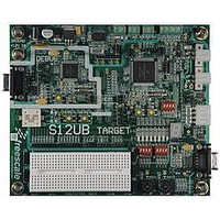
LFEBS12UB
Description
KIT STUDENT LEARNING S12 DG128
Manufacturer
Freescale Semiconductor
Specifications of LFEBS12UB
Architecture
8/16-bit
Code Gen Tools Included
Code Warrior
Silicon Manufacturer
Freescale
Core Architecture
S12
Core Sub-architecture
S12
Silicon Core Number
MC9S12
Silicon Family Name
S12D
Kit Contents
HCS12 DG128 Learning Kit
Rohs Compliant
Yes
Lead Free Status / RoHS Status
Lead free / RoHS Compliant


Chapter 3 Memory Mapping Control (S12XMMCV4)
The reset value of 0xFE ensures that there is a linear EEPROM space available between addresses 0x0800
and 0x0FFF out of reset.
The fixed 1K page 0x0C00–0x0FFF of EEPROM is equivalent to page 255 (page number 0xFF).
3.4
The MMC block performs several basic functions of the S12X sub-system operation: MCU operation
modes, priority control, address mapping, select signal generation and access limitations for the system.
Each aspect is described in the following subsections.
3.4.1
208
Because of an order from the United States International Trade Commission, BGA-packaged product lines and partnumbers
EP[7:0]
indicated here currently are not available from Freescale for import or sale in the United States prior to September 2010
•
•
Field
7–0
Normal single-chip mode
There is no external bus in this mode. The MCU program is executed from the internal memory
and no external accesses are allowed.
Special single-chip mode
This mode is generally used for debugging single-chip operation, boot-strapping or security related
operations. The active background debug mode is in control of the CPU code execution and the
BDM firmware is waiting for serial commands sent through the BKGD pin. There is no external
bus in this mode.
Functional Description
MCU Operating Mode
0
EEPROM Page Index Bits 7–0 — These page index bits are used to select which of the 256 EEPROM array
pages is to be accessed in the EEPROM Page Window.
0
1
0
MC9S12XE-Family Reference Manual , Rev. 1.23
Figure 3-16. EPAGE Address Mapping
Table 3-15. EPAGE Field Descriptions
0
Bit17
Global Address [22:0]
EPAGE Register [7:0]
Bit16
Description
Bit10
Address: CPU Local Address
Bit9
or BDM Local Address
Address [9:0]
Freescale Semiconductor
Bit0
Related parts for LFEBS12UB
Image
Part Number
Description
Manufacturer
Datasheet
Request
R

Part Number:
Description:
Manufacturer:
Freescale Semiconductor, Inc
Datasheet:
Part Number:
Description:
Manufacturer:
Freescale Semiconductor, Inc
Datasheet:
Part Number:
Description:
Manufacturer:
Freescale Semiconductor, Inc
Datasheet:
Part Number:
Description:
Manufacturer:
Freescale Semiconductor, Inc
Datasheet:
Part Number:
Description:
Manufacturer:
Freescale Semiconductor, Inc
Datasheet:
Part Number:
Description:
Manufacturer:
Freescale Semiconductor, Inc
Datasheet:
Part Number:
Description:
Manufacturer:
Freescale Semiconductor, Inc
Datasheet:
Part Number:
Description:
Manufacturer:
Freescale Semiconductor, Inc
Datasheet:
Part Number:
Description:
Manufacturer:
Freescale Semiconductor, Inc
Datasheet:
Part Number:
Description:
Manufacturer:
Freescale Semiconductor, Inc
Datasheet:
Part Number:
Description:
Manufacturer:
Freescale Semiconductor, Inc
Datasheet:
Part Number:
Description:
Manufacturer:
Freescale Semiconductor, Inc
Datasheet:
Part Number:
Description:
Manufacturer:
Freescale Semiconductor, Inc
Datasheet:
Part Number:
Description:
Manufacturer:
Freescale Semiconductor, Inc
Datasheet:
Part Number:
Description:
Manufacturer:
Freescale Semiconductor, Inc
Datasheet: