LFEBS12UB Freescale Semiconductor, LFEBS12UB Datasheet - Page 389
LFEBS12UB
Manufacturer Part Number
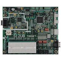
LFEBS12UB
Description
KIT STUDENT LEARNING S12 DG128
Manufacturer
Freescale Semiconductor
Specifications of LFEBS12UB
Architecture
8/16-bit
Code Gen Tools Included
Code Warrior
Silicon Manufacturer
Freescale
Core Architecture
S12
Core Sub-architecture
S12
Silicon Core Number
MC9S12
Silicon Family Name
S12D
Kit Contents
HCS12 DG128 Learning Kit
Rohs Compliant
Yes
Lead Free Status / RoHS Status
Lead free / RoHS Compliant


10.8.2.5
This addressing mode is used to identify the position and size of a bit field for insertion or extraction. The
width and offset are coded in the lower byte of the source register 2, RS2. The content of the upper byte is
ignored. An offset of 0 denotes the right most position and a width of 0 denotes 1 bit. These instructions
are very useful to extract, insert, clear, set or toggle portions of a 16 bit word
10.8.2.6
The XGATE offers a number of additional instructions for flag manipulation, program flow control and
debugging:
10.8.3
Table 10-23
letter implies additional wait cycles if memories or peripherals are not accessible. Memories or peripherals
are not accessible if they are blocked by the S12X_CPU. In addition to this Peripherals are only accessible
every other XGATE cycle. Uppercase letters denote 16 bit operations. Lowercase letters denote 8 bit
operations. The XGATE is able to perform two bus or wait cycles per S12X_CPU cycle.
Freescale Semiconductor
Because of an order from the United States International Trade Commission, BGA-packaged product lines and partnumbers
1. SIF: Set a channel interrupt flag
2. SSEM: Test and set a hardware semaphore
3. CSEM: Clear a hardware semaphore
4. BRK: Software breakpoint
5. NOP: No Operation
6. RTS: Terminate the current thread
indicated here currently are not available from Freescale for import or sale in the United States prior to September 2010
BFEXT
Cycle Notation
show the XGATE access detail notation. Each code letter equals one XGATE cycle. Each
Bit Field Operations
Special Instructions for DMA Usage
15
15
R3,R4,R5 ; R5: W4+1 bits with offset O4, will be extracted from R4 into R3
MC9S12XE-Family Reference Manual Rev. 1.23
Figure 10-26. Bit Field Addressing
Bit Field Insert
7
W4
W4=3, O4=2
5
4
3
3
2
O4
Bit Field Extract
0
0
0
RS2
RS1
RD
Chapter 10 XGATE (S12XGATEV3)
389
Related parts for LFEBS12UB
Image
Part Number
Description
Manufacturer
Datasheet
Request
R

Part Number:
Description:
Manufacturer:
Freescale Semiconductor, Inc
Datasheet:
Part Number:
Description:
Manufacturer:
Freescale Semiconductor, Inc
Datasheet:
Part Number:
Description:
Manufacturer:
Freescale Semiconductor, Inc
Datasheet:
Part Number:
Description:
Manufacturer:
Freescale Semiconductor, Inc
Datasheet:
Part Number:
Description:
Manufacturer:
Freescale Semiconductor, Inc
Datasheet:
Part Number:
Description:
Manufacturer:
Freescale Semiconductor, Inc
Datasheet:
Part Number:
Description:
Manufacturer:
Freescale Semiconductor, Inc
Datasheet:
Part Number:
Description:
Manufacturer:
Freescale Semiconductor, Inc
Datasheet:
Part Number:
Description:
Manufacturer:
Freescale Semiconductor, Inc
Datasheet:
Part Number:
Description:
Manufacturer:
Freescale Semiconductor, Inc
Datasheet:
Part Number:
Description:
Manufacturer:
Freescale Semiconductor, Inc
Datasheet:
Part Number:
Description:
Manufacturer:
Freescale Semiconductor, Inc
Datasheet:
Part Number:
Description:
Manufacturer:
Freescale Semiconductor, Inc
Datasheet:
Part Number:
Description:
Manufacturer:
Freescale Semiconductor, Inc
Datasheet:
Part Number:
Description:
Manufacturer:
Freescale Semiconductor, Inc
Datasheet: