LFEBS12UB Freescale Semiconductor, LFEBS12UB Datasheet - Page 319
LFEBS12UB
Manufacturer Part Number
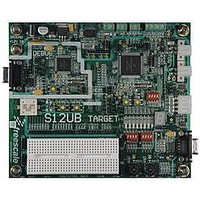
LFEBS12UB
Description
KIT STUDENT LEARNING S12 DG128
Manufacturer
Freescale Semiconductor
Specifications of LFEBS12UB
Architecture
8/16-bit
Code Gen Tools Included
Code Warrior
Silicon Manufacturer
Freescale
Core Architecture
S12
Core Sub-architecture
S12
Silicon Core Number
MC9S12
Silicon Family Name
S12D
Kit Contents
HCS12 DG128 Learning Kit
Rohs Compliant
Yes
Lead Free Status / RoHS Status
Lead free / RoHS Compliant


8.3.2.7
There is a dedicated control register for each of the state sequencer states 1 to 3 that determines if
transitions from that state are allowed, depending upon comparator matches or tag hits, and defines the
next state for the state sequencer following a match. The three debug state control registers are located at
the same address in the register address map (0x0027). Each register can be accessed using the COMRV
bits in DBGC1 to blend in the required register. The COMRV = 11 value blends in the match flag register
(DBGMFR).
8.3.2.7.1
Read: If COMRV[1:0] = 00
Write: If COMRV[1:0] = 00 and S12XDBG is not armed.
This register is visible at 0x0027 only with COMRV[1:0] = 00. The state control register 1 selects the
targeted next state whilst in State1. The matches refer to the match channels of the comparator match
control logic as depicted in
by setting the comparator enable bit in the associated DBGXCTL control register.
Freescale Semiconductor
Address: 0x0027
Because of an order from the United States International Trade Commission, BGA-packaged product lines and partnumbers
SC[3:0]
Reset
indicated here currently are not available from Freescale for import or sale in the United States prior to September 2010
Field
3–0
SC[3:0]
W
R
0000
0001
0010
0011
These bits select the targeted next state whilst in State1, based upon the match event.
Debug State Control Registers
0
0
7
Debug State Control Register 1 (DBGSCR1)
= Unimplemented or Reserved
Figure 8-9. Debug State Control Register 1 (DBGSCR1)
0
0
6
Table 8-21. State Control Register Access Encoding
Figure 8-1
Table 8-23. State1 Sequencer Next State Selection
COMRV
MC9S12XE-Family Reference Manual Rev. 1.23
Table 8-22. DBGSCR1 Field Descriptions
00
01
10
11
Match2 triggers to State2....... Other matches have no effect
5
0
0
and described in
Any match triggers to Final State
Visible State Control Register
0
0
Any match triggers to state2
Any match triggers to state3
4
Description
Section
Description
DBGSCR1
DBGSCR2
DBGSCR3
DBGMFR
SC3
0
3
8.3.2.8.1”. Comparators must be enabled
Chapter 8 S12X Debug (S12XDBGV3) Module
SC2
2
0
SC1
0
1
SC0
0
0
319
Related parts for LFEBS12UB
Image
Part Number
Description
Manufacturer
Datasheet
Request
R

Part Number:
Description:
Manufacturer:
Freescale Semiconductor, Inc
Datasheet:
Part Number:
Description:
Manufacturer:
Freescale Semiconductor, Inc
Datasheet:
Part Number:
Description:
Manufacturer:
Freescale Semiconductor, Inc
Datasheet:
Part Number:
Description:
Manufacturer:
Freescale Semiconductor, Inc
Datasheet:
Part Number:
Description:
Manufacturer:
Freescale Semiconductor, Inc
Datasheet:
Part Number:
Description:
Manufacturer:
Freescale Semiconductor, Inc
Datasheet:
Part Number:
Description:
Manufacturer:
Freescale Semiconductor, Inc
Datasheet:
Part Number:
Description:
Manufacturer:
Freescale Semiconductor, Inc
Datasheet:
Part Number:
Description:
Manufacturer:
Freescale Semiconductor, Inc
Datasheet:
Part Number:
Description:
Manufacturer:
Freescale Semiconductor, Inc
Datasheet:
Part Number:
Description:
Manufacturer:
Freescale Semiconductor, Inc
Datasheet:
Part Number:
Description:
Manufacturer:
Freescale Semiconductor, Inc
Datasheet:
Part Number:
Description:
Manufacturer:
Freescale Semiconductor, Inc
Datasheet:
Part Number:
Description:
Manufacturer:
Freescale Semiconductor, Inc
Datasheet:
Part Number:
Description:
Manufacturer:
Freescale Semiconductor, Inc
Datasheet: