LFEBS12UB Freescale Semiconductor, LFEBS12UB Datasheet - Page 716
LFEBS12UB
Manufacturer Part Number
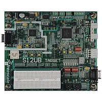
LFEBS12UB
Description
KIT STUDENT LEARNING S12 DG128
Manufacturer
Freescale Semiconductor
Specifications of LFEBS12UB
Architecture
8/16-bit
Code Gen Tools Included
Code Warrior
Silicon Manufacturer
Freescale
Core Architecture
S12
Core Sub-architecture
S12
Silicon Core Number
MC9S12
Silicon Family Name
S12D
Kit Contents
HCS12 DG128 Learning Kit
Rohs Compliant
Yes
Lead Free Status / RoHS Status
Lead free / RoHS Compliant


Chapter 19 Pulse-Width Modulator (S12PWM8B8CV1)
19.4.2.2
Each channel has a polarity bit to allow starting a waveform cycle with a high or low signal. This is shown
on the block diagram as a mux select of either the Q output or the Q output of the PWM output flip flop.
When one of the bits in the PWMPOL register is set, the associated PWM channel output is high at the
beginning of the waveform, then goes low when the duty count is reached. Conversely, if the polarity bit
is zero, the output starts low and then goes high when the duty count is reached.
19.4.2.3
Dedicated period and duty registers exist for each channel and are double buffered so that if they change
while the channel is enabled, the change will NOT take effect until one of the following occurs:
In this way, the output of the PWM will always be either the old waveform or the new waveform, not some
variation in between. If the channel is not enabled, then writes to the period and duty registers will go
directly to the latches as well as the buffer.
A change in duty or period can be forced into effect “immediately” by writing the new value to the duty
and/or period registers and then writing to the counter. This forces the counter to reset and the new duty
and/or period values to be latched. In addition, since the counter is readable, it is possible to know where
the count is with respect to the duty value and software can be used to make adjustments
19.4.2.4
Each channel has a dedicated 8-bit up/down counter which runs at the rate of the selected clock source (see
Section 19.4.1, “PWM Clock Select”
two registers, a duty register and a period register as shown in
matches the duty register, the output flip-flop changes state, causing the PWM waveform to also change
state. A match between the PWM counter and the period register behaves differently depending on what
output mode is selected as shown in
Outputs”
Each channel counter can be read at anytime without affecting the count or the operation of the PWM
channel.
Any value written to the counter causes the counter to reset to $00, the counter direction to be set to up,
the immediate load of both duty and period registers with values from the buffers, and the output to change
according to the polarity bit. When the channel is disabled (PWMEx = 0), the counter stops. When a
716
Because of an order from the United States International Trade Commission, BGA-packaged product lines and partnumbers
indicated here currently are not available from Freescale for import or sale in the United States prior to September 2010
•
•
•
The effective period ends
The counter is written (counter resets to $00)
The channel is disabled
and
PWM Polarity
PWM Period and Duty
PWM Timer Counters
Section 19.4.2.6, “Center Aligned
When forcing a new period or duty into effect immediately, an irregular
PWM cycle can occur.
Depending on the polarity bit, the duty registers will contain the count of
either the high time or the low time.
MC9S12XE-Family Reference Manual , Rev. 1.23
Figure 19-19
for the available clock sources and rates). The counter compares to
Outputs”.
NOTE
and described in
Figure
Section 19.4.2.5, “Left Aligned
19-19. When the PWM counter
Freescale Semiconductor
Related parts for LFEBS12UB
Image
Part Number
Description
Manufacturer
Datasheet
Request
R

Part Number:
Description:
Manufacturer:
Freescale Semiconductor, Inc
Datasheet:
Part Number:
Description:
Manufacturer:
Freescale Semiconductor, Inc
Datasheet:
Part Number:
Description:
Manufacturer:
Freescale Semiconductor, Inc
Datasheet:
Part Number:
Description:
Manufacturer:
Freescale Semiconductor, Inc
Datasheet:
Part Number:
Description:
Manufacturer:
Freescale Semiconductor, Inc
Datasheet:
Part Number:
Description:
Manufacturer:
Freescale Semiconductor, Inc
Datasheet:
Part Number:
Description:
Manufacturer:
Freescale Semiconductor, Inc
Datasheet:
Part Number:
Description:
Manufacturer:
Freescale Semiconductor, Inc
Datasheet:
Part Number:
Description:
Manufacturer:
Freescale Semiconductor, Inc
Datasheet:
Part Number:
Description:
Manufacturer:
Freescale Semiconductor, Inc
Datasheet:
Part Number:
Description:
Manufacturer:
Freescale Semiconductor, Inc
Datasheet:
Part Number:
Description:
Manufacturer:
Freescale Semiconductor, Inc
Datasheet:
Part Number:
Description:
Manufacturer:
Freescale Semiconductor, Inc
Datasheet:
Part Number:
Description:
Manufacturer:
Freescale Semiconductor, Inc
Datasheet:
Part Number:
Description:
Manufacturer:
Freescale Semiconductor, Inc
Datasheet: