LFEBS12UB Freescale Semiconductor, LFEBS12UB Datasheet - Page 141
LFEBS12UB
Manufacturer Part Number
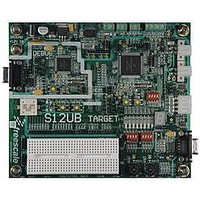
LFEBS12UB
Description
KIT STUDENT LEARNING S12 DG128
Manufacturer
Freescale Semiconductor
Specifications of LFEBS12UB
Architecture
8/16-bit
Code Gen Tools Included
Code Warrior
Silicon Manufacturer
Freescale
Core Architecture
S12
Core Sub-architecture
S12
Silicon Core Number
MC9S12
Silicon Family Name
S12D
Kit Contents
HCS12 DG128 Learning Kit
Rohs Compliant
Yes
Lead Free Status / RoHS Status
Lead free / RoHS Compliant


1. Read: Anytime.
2.3.45
Freescale Semiconductor
Function
Address 0x0258
Write: Anytime.
Altern.
Field
Reset
PTP
PTP
PTP
PTP
7
6
5
4
W
R
Port P general purpose input/output data—Data Register
Port P pin 6 is associated with the PWM output channel 7 and the SCK signal of SPI2.
The PWM function takes precedence over the SPI2 and the general purpose I/O function if the PWM channel 7 is
enabled. The SPI2 function takes precedence of the general purpose I/O function if the routed SPI2 is enabled.
When not used with the alternative functions, these pins can be used as general purpose I/O.
If the associated data direction bits of these pins are set to 1, a read returns the value of the port register, otherwise
the buffered pin input state is read.
Port P general purpose input/output data—Data Register
Port P pin 6 is associated with the PWM output channel 6 and the SS signal of SPI2.
The PWM function takes precedence over the SPI2 and the general purpose I/O function if the PWM channel 6 is
enabled. The SPI2 function takes precedence of the general purpose I/O function if the routed SPI2 is enabled.
When not used with the alternative functions, these pins can be used as general purpose I/O.
If the associated data direction bits of these pins are set to 1, a read returns the value of the port register, otherwise
the buffered pin input state is read.
Port P general purpose input/output data—Data Register
Port P pin 5 is associated with the PWM output channel 5 and the MOSI signal of SPI2.
The PWM function takes precedence over the SPI2 and the general purpose I/O function if the PWM channel 5 is
enabled. The SPI2 function takes precedence of the general purpose I/O function if the routed SPI2 is enabled.
When not used with the alternative functions, these pins can be used as general purpose I/O.
If the associated data direction bits of these pins are set to 1, a read returns the value of the port register, otherwise
the buffered pin input state is read.
Port P general purpose input/output data—Data Register
Port P pin 4 is associated with the PWM output channel 4 and the MISO signal of SPI2.
The PWM function takes precedence over the SPI2 and the general purpose I/O function if the PWM channel 4 is
enabled. The SPI2 function takes precedence of the general purpose I/O function if the routed SPI2 is enabled.
When not used with the alternative functions, these pins can be used as general purpose I/O.
If the associated data direction bits of these pins are set to 1, a read returns the value of the port register, otherwise
the buffered pin input state is read.
PWM7
PTP7
SCK2
Port P Data Register (PTP)
0
7
PWM6
PTP6
SS2
0
6
Table 2-41. PTP Register Field Descriptions
MC9S12XE-Family Reference Manual , Rev. 1.23
Figure 2-43. Port P Data Register (PTP)
PWM5
MOSI2
PTP5
0
5
MISO2
PWM4
PTP4
0
4
Description
PWM3
PTP3
SS1
3
0
Chapter 2 Port Integration Module (S12XEPIMV1)
PWM2
SCK1
PTP2
0
2
Access: User read/write
MOSI1
PWM1
PTP1
0
1
MISO1
PWM0
PTP0
0
0
141
(1)
Related parts for LFEBS12UB
Image
Part Number
Description
Manufacturer
Datasheet
Request
R

Part Number:
Description:
Manufacturer:
Freescale Semiconductor, Inc
Datasheet:
Part Number:
Description:
Manufacturer:
Freescale Semiconductor, Inc
Datasheet:
Part Number:
Description:
Manufacturer:
Freescale Semiconductor, Inc
Datasheet:
Part Number:
Description:
Manufacturer:
Freescale Semiconductor, Inc
Datasheet:
Part Number:
Description:
Manufacturer:
Freescale Semiconductor, Inc
Datasheet:
Part Number:
Description:
Manufacturer:
Freescale Semiconductor, Inc
Datasheet:
Part Number:
Description:
Manufacturer:
Freescale Semiconductor, Inc
Datasheet:
Part Number:
Description:
Manufacturer:
Freescale Semiconductor, Inc
Datasheet:
Part Number:
Description:
Manufacturer:
Freescale Semiconductor, Inc
Datasheet:
Part Number:
Description:
Manufacturer:
Freescale Semiconductor, Inc
Datasheet:
Part Number:
Description:
Manufacturer:
Freescale Semiconductor, Inc
Datasheet:
Part Number:
Description:
Manufacturer:
Freescale Semiconductor, Inc
Datasheet:
Part Number:
Description:
Manufacturer:
Freescale Semiconductor, Inc
Datasheet:
Part Number:
Description:
Manufacturer:
Freescale Semiconductor, Inc
Datasheet:
Part Number:
Description:
Manufacturer:
Freescale Semiconductor, Inc
Datasheet: