LFEBS12UB Freescale Semiconductor, LFEBS12UB Datasheet - Page 767
LFEBS12UB
Manufacturer Part Number
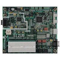
LFEBS12UB
Description
KIT STUDENT LEARNING S12 DG128
Manufacturer
Freescale Semiconductor
Specifications of LFEBS12UB
Architecture
8/16-bit
Code Gen Tools Included
Code Warrior
Silicon Manufacturer
Freescale
Core Architecture
S12
Core Sub-architecture
S12
Silicon Core Number
MC9S12
Silicon Family Name
S12D
Kit Contents
HCS12 DG128 Learning Kit
Rohs Compliant
Yes
Lead Free Status / RoHS Status
Lead free / RoHS Compliant


21.3.2
This section consists of register descriptions in address order. Each description includes a standard register
diagram with an associated figure number. Details of register bit and field function follow the register
diagrams, in bit order.
21.3.2.1
Read: Anytime
Write: Anytime
Freescale Semiconductor
Module Base +0x0000
Because of an order from the United States International Trade Commission, BGA-packaged product lines and partnumbers
Reset
SPTIE
indicated here currently are not available from Freescale for import or sale in the United States prior to September 2010
MSTR
CPHA
CPOL
Field
SPIE
SPE
7
6
5
4
3
2
W
R
Register Descriptions
SPIE
SPI Interrupt Enable Bit — This bit enables SPI interrupt requests, if SPIF or MODF status flag is set.
0 SPI interrupts disabled.
1 SPI interrupts enabled.
SPI System Enable Bit — This bit enables the SPI system and dedicates the SPI port pins to SPI system
functions. If SPE is cleared, SPI is disabled and forced into idle state, status bits in SPISR register are reset.
0 SPI disabled (lower power consumption).
1 SPI enabled, port pins are dedicated to SPI functions.
SPI Transmit Interrupt Enable — This bit enables SPI interrupt requests, if SPTEF flag is set.
0 SPTEF interrupt disabled.
1 SPTEF interrupt enabled.
SPI Master/Slave Mode Select Bit — This bit selects whether the SPI operates in master or slave mode.
Switching the SPI from master to slave or vice versa forces the SPI system into idle state.
0 SPI is in slave mode.
1 SPI is in master mode.
SPI Clock Polarity Bit — This bit selects an inverted or non-inverted SPI clock. To transmit data between SPI
modules, the SPI modules must have identical CPOL values. In master mode, a change of this bit will abort a
transmission in progress and force the SPI system into idle state.
0 Active-high clocks selected. In idle state SCK is low.
1 Active-low clocks selected. In idle state SCK is high.
SPI Clock Phase Bit — This bit is used to select the SPI clock format. In master mode, a change of this bit will
abort a transmission in progress and force the SPI system into idle state.
0 Sampling of data occurs at odd edges (1,3,5,...) of the SCK clock.
1 Sampling of data occurs at even edges (2,4,6,...) of the SCK clock.
SPI Control Register 1 (SPICR1)
0
7
SPE
0
6
Figure 21-3. SPI Control Register 1 (SPICR1)
MC9S12XE-Family Reference Manual Rev. 1.23
Table 21-2. SPICR1 Field Descriptions
SPTIE
5
0
MSTR
0
4
Description
CPOL
0
3
Chapter 21 Serial Peripheral Interface (S12SPIV5)
CPHA
2
1
SSOE
0
1
LSBFE
0
0
767
Related parts for LFEBS12UB
Image
Part Number
Description
Manufacturer
Datasheet
Request
R

Part Number:
Description:
Manufacturer:
Freescale Semiconductor, Inc
Datasheet:
Part Number:
Description:
Manufacturer:
Freescale Semiconductor, Inc
Datasheet:
Part Number:
Description:
Manufacturer:
Freescale Semiconductor, Inc
Datasheet:
Part Number:
Description:
Manufacturer:
Freescale Semiconductor, Inc
Datasheet:
Part Number:
Description:
Manufacturer:
Freescale Semiconductor, Inc
Datasheet:
Part Number:
Description:
Manufacturer:
Freescale Semiconductor, Inc
Datasheet:
Part Number:
Description:
Manufacturer:
Freescale Semiconductor, Inc
Datasheet:
Part Number:
Description:
Manufacturer:
Freescale Semiconductor, Inc
Datasheet:
Part Number:
Description:
Manufacturer:
Freescale Semiconductor, Inc
Datasheet:
Part Number:
Description:
Manufacturer:
Freescale Semiconductor, Inc
Datasheet:
Part Number:
Description:
Manufacturer:
Freescale Semiconductor, Inc
Datasheet:
Part Number:
Description:
Manufacturer:
Freescale Semiconductor, Inc
Datasheet:
Part Number:
Description:
Manufacturer:
Freescale Semiconductor, Inc
Datasheet:
Part Number:
Description:
Manufacturer:
Freescale Semiconductor, Inc
Datasheet:
Part Number:
Description:
Manufacturer:
Freescale Semiconductor, Inc
Datasheet: